


Knife-edge scanning microscope (KESM)
Technical Report: B. H. McCormick, Development of the Brain Tissue Scanner, Technical Report, Brain Networks Laboratory, Department of Computer Science, Texas A&M University, College Station, Texas, 2002. [PDF]
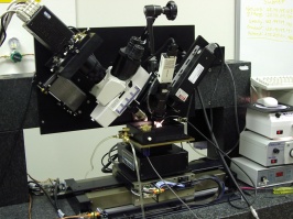
Figure 1: The knife-edge scanning microscope: microscope and camera assembly (left; slanted), light source (white light illuminator) and knife assembly (right; slanted), and the stage (center; bottom). [More images] |
Knife-edge scanning
Knife-edge scanning, introduced in the KESM instrument, not only preserves image registration throughout the depth of the specimen block but also isolates the tissue above the knife from that below to eliminate undesirable events (back-scattering of light and bleaching of fluorescent-stained tissue below the knife). Knife-edge scanning supports all known forms of microscopy (absorption imaging using transmitted light, and reflected light imaging using bright-field, dark-field, DIC, and GFP fluorescence).
Consider the acquisition of volume data representing a plastic-embedded mouse brain (15mm A-P, 12mm M-L, 6mm D-V). A 40X objective has a field of view (knife width) of 0.625mm. Sixteen strips (each 0.625mm wide by 15mm long) are cut for each Z-axis section (like plowing a field). For a (Z-axis) block height of 6mm, 12,000 sections must be cut, each 0.5µm thick. The integrated tissue ribbon length (15mm/strip x 16strips/section x 12,000sections/mouse brain) is 2.9km.
 |
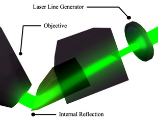 |
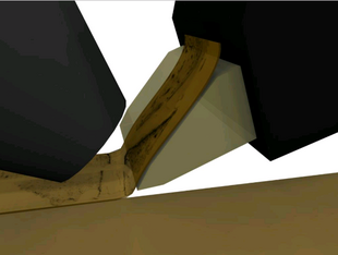
| Figure 2: Specimen undergoing sectioning by the KESM. (Thickness of the section is exaggerated.) | Figure 3: Diamond knife collimator supporting transmission illumination (white light). |
The tissue ribbon is line-sampled at 300nm resolution, near the Nyquist rate for an ideal optical resolution of (0.77)(532nm)=(0.80NA) = 512nm. The tissue ribbon can be sampled at 11mm/s by line sampling at 44kHz, the camera maximum. Sampling the 2.9km tissue ribbon requires 265,000s = 73hr. Because mice brains are not cubical, stage return takes time, etc., we add 50% overhead. As shown in Figure 3, the KESM supports two illumination schemes, depending on the orientation of light rays produced by laser line-generators. Light rays starting parallel to the green line emerge normal to the knife collimator. This trans-illumination scheme is used for absorption imaging (e.g., with Golgi stain). Light rays starting parallel to the blue line (red line, with one additional internal reflection) emerge from the knife parallel to the blue (red) line, at a considerable angle to the optical axis of the objective. This epi-illumination scheme works well for fluorescence imaging, limiting the excitation illumination collected by the objective. Fluorescence illumination is spherically symmetric (i.e., independent of the incident angle of excitation illumination) and so is still captured by the objective.
Precision positioning system and ultramicrotome
(Aerotech Inc., Pittsburgh, Pennsylvenia; Micro Star Technology, Huntsville, Texas). The specimen block is mounted atop a three-axis precision stage. The custom diamond knife cuts serial thin sections, typically 0.5mm thick. The sectioning process destroys the tissue block. Following current practice in semiconductor inspection instrumentation, this system provides an air-bearing stage for the X-axis (cutting axis), and encoding resolution of 20nm for the X- and Y-axes and 25nm for the vertical Z-axis. This insures registration of images from consecutive serial sections into an aligned image stack, or volume data set.Image capture system
(DALSA, Canada; EPIX, Inc., Buffalo Grove, IL; Micro Star Technology, Huntsville, Texas): Either of two line-scan cameras (Dalsa, CT-F3-4096 pixels or Dalsa, CL-T5-2048 pixels, color) images the newly-cut thin section just beyond the knife edge, prior to its subsequent deformation. The microscope objective images the edge of the knife. The objective is aligned perpendicular to the top surface of the diamond knife (and hence its axis is oriented at 45° to the vertical). The tissue is imaged using the recently introduced Nikon CF160 water immersion objectives: the CFl Fluor 10X (NA 0.3) and CFl Fluor 40X (NA 0.8). These objectives have two advantages: They fit within the fold between the uncut and newly cut tissue, and being water-immersion, have higher numerical aperture. For surveying rodent brain at lower resolution in air, CFl Apo 4X and 2X objectives are also provided.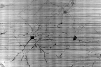 |
 |
| Figure 4: Golgi-stained tissue sample (superimposed). [More data] | Figure 5: Nissl-stained tissue sample. The choroid plexus (left) and the hippocampal fold (right) are visible.[More data] |
A choice of diode laser line generators (green: 532nm, 100mW or blue: 473nm, 30mW; StockerYale, Canada) illuminates tissue at the diamond knife tip with 30-100mm wide strip of intense illumination running the length of the knife-edge. The diamond knife tip serves dual use: (1) as an optical element (prism in the microscope collimation optics) and (2) for physical sectioning (Figure 3). The intensity of the knife-edge illumination allows line sampling at 44kHz (for the Dalsa CT-F3 camera). The camera is triggered at 300nm increments along the X-axis for high-resolution imaging, using the Synchronized Pulse Output facility of the stage controller. The stage velocity is kept constant at 11mm/s; the stage position is encoded at 20nm resolution. Alignment of the laser line generator, diamond knife-edge, microscope optical train, and line scan camera is established by a custom collimating assembly (Micro Star Technologies, Huntsville, Texas).
Embedded computer system
(Dell Computer Corporation; EPIX Inc., Buffalo Grove, IL): Digital video from the multi-tapped linear CCD array of the CT-F3 camera is delivered via 8 channels at 25MHB/s each to a Dell PowerEdge 2550 server. Camera interface cards (two for the Dalsa CT-F3-4096 line scan camera; one for the Dalsa CL-T5-2048 color line scan camera) provided by Epix, Inc. store this data in the dual processor. The initial configuration of the KESM uses five Dell dual processor servers, each 1.1 to 1.3 GHz, with 2GB memory. Integrated hard drive storage of the system is 1 Terabyte. A Cisco 8-port switch using Gigabit transmission interconnects the servers and a parallel computer in the neighboring PARASOL laboratory.Related Links: Publications; Seminars; Sponsors; Software; Multimedia gallery; *KESM specifications;
References
[1] McCormick, B.H., Brain Tissue Scanner enables brain microstructure surveys, Neurocomputing, 44-46:1113-1118, 2002. [2] McCormick, B.H., Development of the Brain Tissue Scanner, Technical Report, Department of Computer Science, Texas A&M University, College Station, Texas, March 18, 2002 [PDF].Contact us | Home
© Copyright 2004 Brain Networks Laboratory | Department of Computer Science
Dwight Look College of Engineering | Texas A&M University | Texas Engineering Experiment Station

