Due Tuesday 4/13 at 11:59 pm. You must work individually.
NOTE: For maximum compatibility with student computers/drivers, we are only going to use OpenGL 2.1.
(The graininess is due to the video compression – better quality video here.)
There is no base code provided for this assignment. Please start with your previous lab/assignment code. Please come see the instructor or the TA if you need help completing your previous assignment.
Start with your A3 or A4 code.
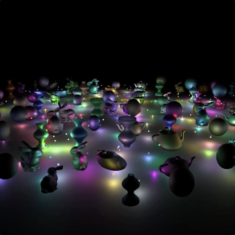
Add at least 100 objects in the scene.
Add at least 10 lights, each with a color.
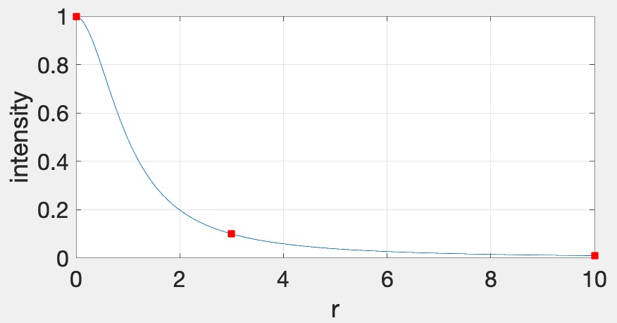
glClearColor(0.0f, 0.0f, 0.0f, 1.0f); in the init function.glm::vec3s to the fragment shader. You can use the following syntax: glUniform3fv(uniformID, count, value_ptr(array[0]));, where uniformID is the ID pointing to the uniform variable in the shader (e.g., prog->getUniform("foo"))), count is the array length, and array is the array of glm::vec3s. In the shader, the array should be declared as uniform vec3 foo[10], assuming that count=10.Now add attenuation to the lights. We’re going to use the standard quadratic attenuation model in OpenGL: \[ A = \frac{1}{A_0 + A_1 r + A_2 r^2}, \] where \(r\) is the distance between the fragment and the light, and \(A_0\), \(A_1\), \(A_2\) are the constant, linear, and quadratic attenuation factors. For this part of the assignment, we want the light to fall off to \(10\)% of its strength at \(r=3\) and to \(1\)% at \(r=10\), which gives us \(A_0 = 1.0\), \(A_1 = 0.0429\), and \(A_2 = 0.9857\). The color at the fragment should be scaled by this attenuation value.
 vec3 fragColor = ke; // emissive color of the object (see below)
 for(...) { // for each light
     float diffuse = ...;
     float specular = ...;
     vec3 color = lightColor * (kd * diffuse + ks * specular);
     float attenuation = 1.0 / (A0 + ...);
     fragColor += color * attenuation;
 }
Each light should be displayed as a sphere, using the same fragment shader as everything else. We’ll use the “emmissive” color, \(k_e\), for this, which is the color that the light is emitting. This value should be set to the light color when rendering the sphere for the light and \((0,0,0)\) for everything else. Putting everything together, the fragment color for all objects and lights should be computed as follows: \[ \vec{k}_e + \sum_i \vec{L}_i \odot \frac{\vec{k}_d \max(0, \hat{n} \cdot \hat{l}_i) + \vec{k}_s \max(0, (\hat{n} \cdot \hat{h}_i)^s)}{A_0 + A_1 r_i + A_2 r_i^2}, \] where \(i\) is the ith light. The \(\odot\) notation indicates that the multiplication should be done component-wise, for R, G, and B. This equation allows us to use a single shader to render everything in the scene – the lights will be colored using \(k_e\), and other objects will be colored with attenuated Blinn-Phong. To summarize:
Rather than changing the scale of the bunny over time as in A4, rotate it around its vertical axis. As in A4, the overall scale of the bunny should still be randomized, and the bunny should touch the floor but not intersect it.
In this image (and the following), I am using only one light to better illustrate the motion.
Rather than changing the scale of the teapot over time as in A4, shear it so that it sways from side to side. The teapot should look like it is glued to the floor. As in A4, the overall scale of the teapot should still be randomized.
Add a bouncing sphere, following the steps outlined in Lab 10. The sphere should have a randomized radius, and it should touch the floor but not intersect it. When the sphere is moving up or down, its scale in X and Z should be made smaller to achieve “squash and stretch”. The geometry of the sphere should be created and stored in memory just once in the init() function. To display multiple spheres in the scene, use different transformation matrices passed in as uniform variables.
Add a surface of revolution, following the steps outlined in Lab 11. First, implement a static surface on the CPU and then move the computation over to the GPU to allow a dynamic surface. Like the sphere, the vertex attributes of the surface of revolution should be created just once in the init() function. To display multiple surfaces of revolution in the scene, use different transformation matrices passed in as uniform variables. Just like the other objects in the scene, the surface-of-revolution objects should just touch the ground.
We are now going to implement deferred rendering. Since this step requires render to texture and multiple render targets, it may help to complete Lab 12 first. Deferred rendering will require substantial overhauling of your code base, so you should make sure to apply source control so that you can easily get back to your old code if needed.
In deferred rendering, we use two passes. In the first pass, we render to multiple render targets to create textures that hold all the information needed to compute the color of each fragment. In the second pass, we render a view-aligned quad with the textures from the first pass, and then do the actual lighting computation in the fragment shader.
The four images below show the four textures we need to generate in the first pass. The size of these textures should be the same as the onscreen framebuffer size, which can be obtained with glfwGetFramebufferSize(...). (The default size is 640 x 480; later, support for resizing the window will be added.)
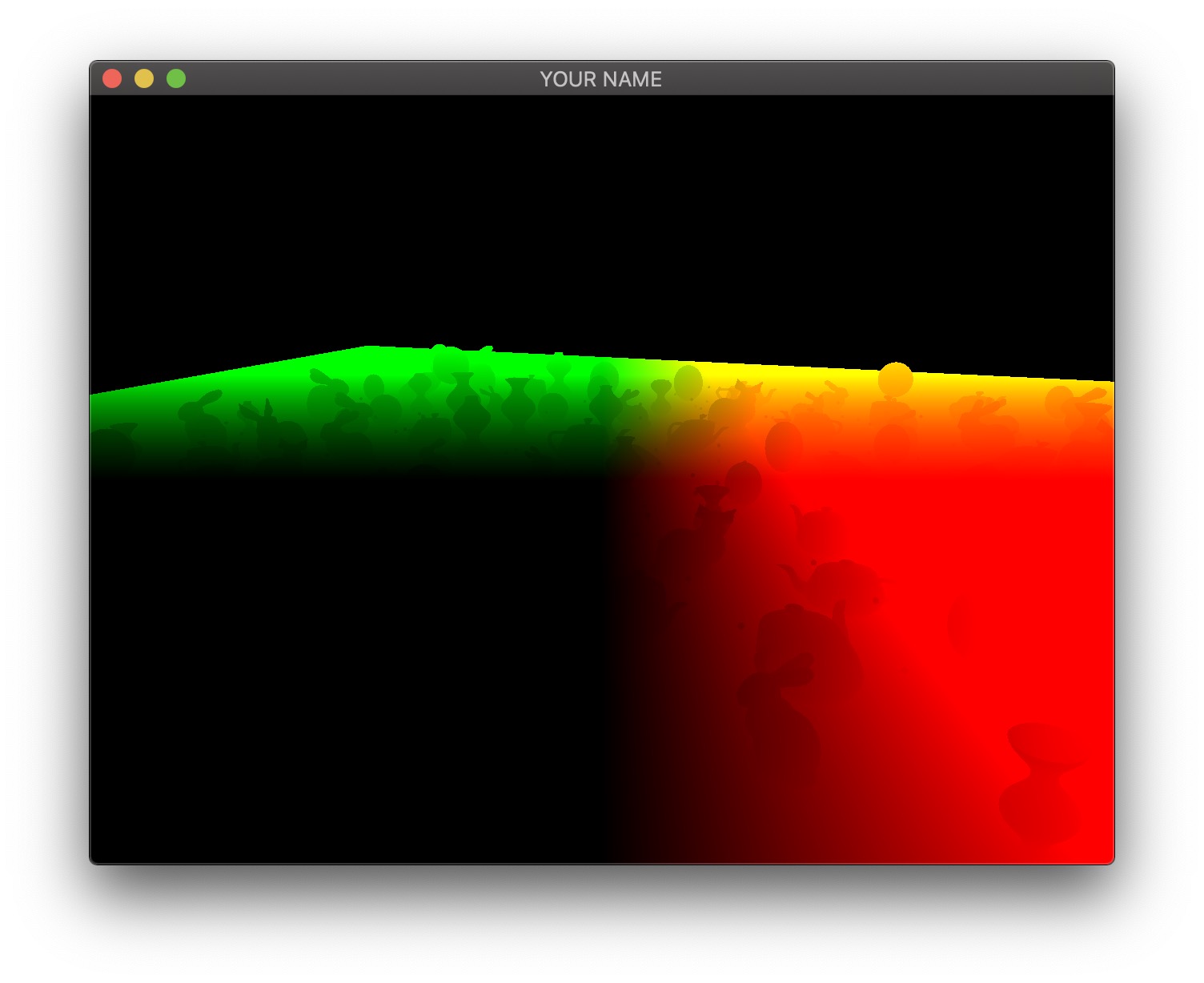
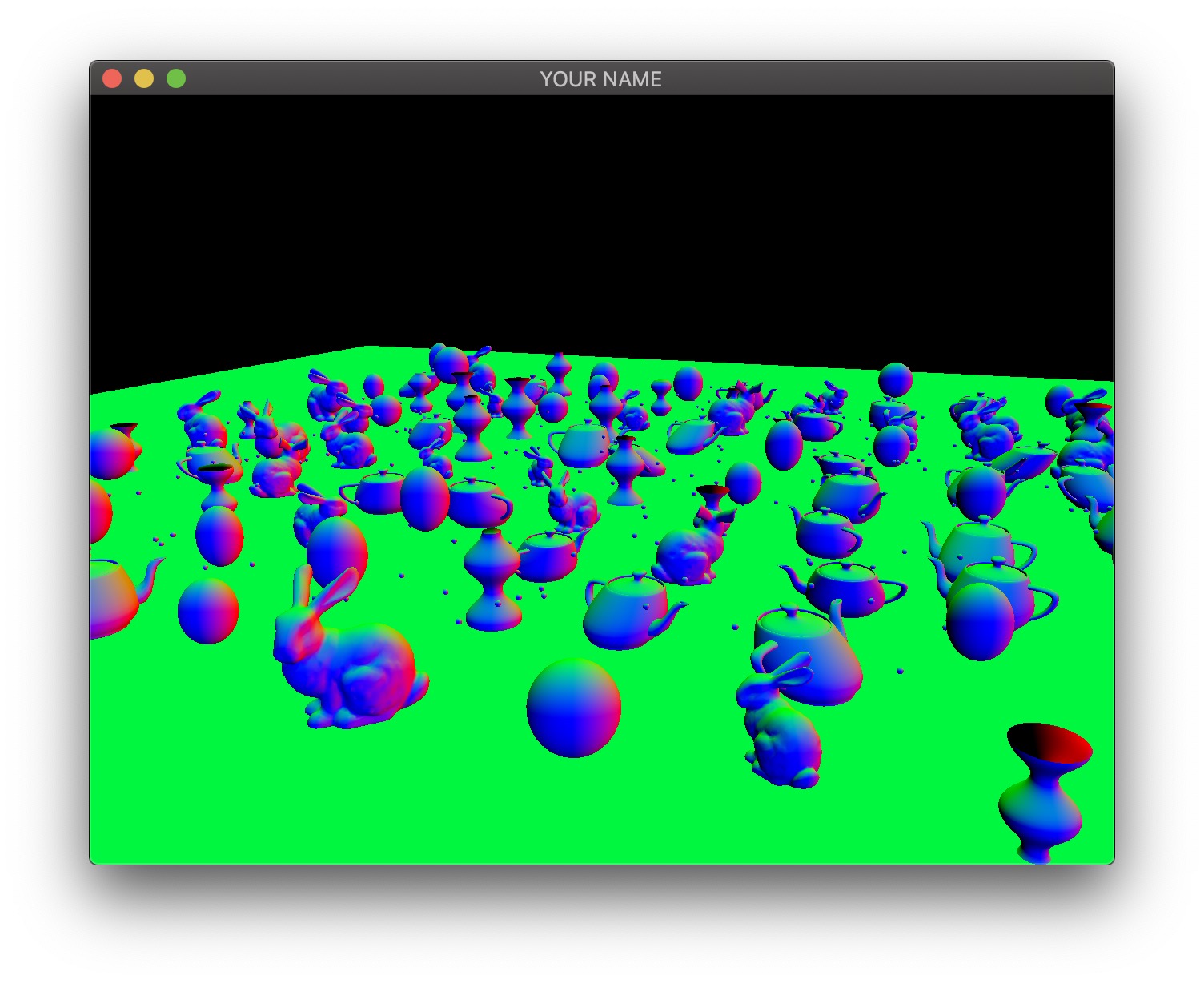
The first image is the camera-space position of all of the fragments. In this visualization, the position \((x,y,z)\) is coded with \((r,g,b)\). Since RGB needs to be between \(0\) and \(1\), the visualization shows a black area in the lower left, corresponding to the region where the camera-space positions are all negative. Also, since the camera-space Z coordinate of all of these fragments are negative, there is no blue component in the color output of any of the fragments.
The second image is the camera-space normal of all of the fragments. As before, the normal’s \((x,y,z)\) is coded with \((r,g,b)\). Fragments whose normals are pointing to the right in camera-space are colored red, those whose normals are pointing up are colored green, and those whose normals are pointing toward the camera are colored blue.
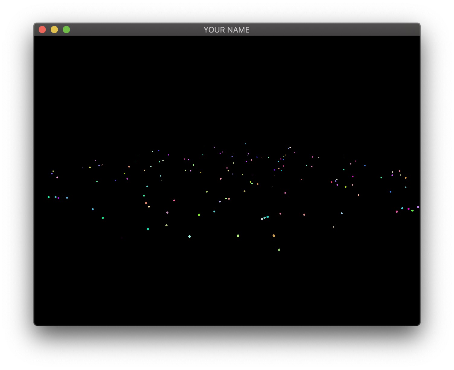
The third image is the emissive color of all the fragments. In this image, I have 200 randomly colored lights, but in your code, you may only have a small number of lights.
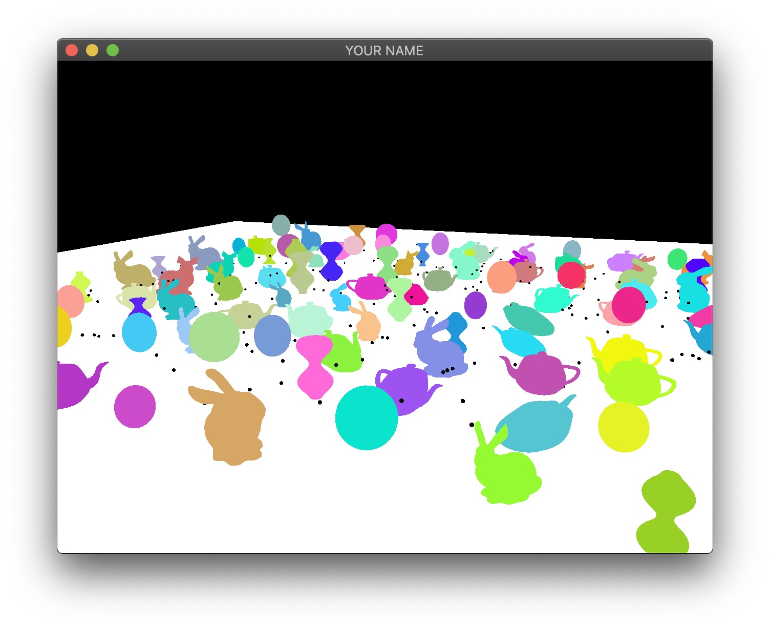
The fourth image is the diffuse color of all the fragments.
These four textures must be generated as the output of the first pass. To do so, first, change the texture format in your C++ code to use floats instead of unsigned bytes:
// L12
glGenTextures(1, &texture);
glBindTexture(GL_TEXTURE_2D, texture);
glTexImage2D(GL_TEXTURE_2D, 0, GL_RGBA8, width, height, 0, GL_RGBA, GL_UNSIGNED_BYTE, NULL);
...
// A5: replace the last line above with this:
glTexImage2D(GL_TEXTURE_2D, 0, GL_RGB16F, width, height, 0, GL_RGB, GL_FLOAT, NULL);
In this assignment, there are four textures, so the line above must be used four times. The fragment shader of the first pass can now write floating point values to the four textures:
#version 120

varying vec3 vPos; // in camera space
varying vec3 vNor; // in camera space

uniform vec3 ke;
uniform vec3 kd;

void main()
{
    gl_FragData[0].xyz = vPos;
    gl_FragData[1].xyz = vNor;
    gl_FragData[2].xyz = ke;
    gl_FragData[3].xyz = kd;
}
The vertex shaders for the first pass depends on what is being drawn. Bunny, teapot, and sphere should be drawn with a simple vertex shader that transforms the position and normal into camera space (vPos and vNor in the fragment shader above). Surface of revolution will require another vertex shader.
In the second pass, we draw a view-aligned quad that completely fills the screen. In this stage of the assignment, we can simply draw a unit square somewhere close enough to the camera so that it ends up covering the whole screen. The vertex shader for the second pass is very simple:
#version 120

uniform mat4 P;
uniform mat4 MV;

attribute vec4 aPos;

void main()
{
    gl_Position = P * (MV * aPos);
}
This vertex shader simply transforms the vertex position from model space to clip space. The fragment shader will use the textures created in the first pass to compute the final fragment colors that end up on the screen. Rather than using the texture coordinates of the quad, we can compute them in the fragment shader using the keyword gl_FragCoord, which stores the window relative coordinate values for the fragment. Dividing this by the window size gives the correct texture coordinates, which is \((0,0)\) at the lower left corner and \((1,1)\) at the upper right corner. Using these texture coordinates, read from the four textures and then calculate the color of the fragment. Additionally, you need to pass in the light information to this fragment shader as uniform variables (e.g., light positions and colors).
#version 120

uniform sampler2D posTexture;
uniform sampler2D norTexture;
uniform sampler2D keTexture;
uniform sampler2D kdTexture;
uniform vec2 windowSize;

... // more uniforms for lighting

void main()
{
    vec2 tex;
    tex.x = gl_FragCoord.x/windowSize.x;
    tex.y = gl_FragCoord.y/windowSize.y;

    // Fetch shading data
    vec3 pos = texture2D(posTexture, tex).rgb;
    vec3 nor = texture2D(norTexture, tex).rgb;
    vec3 ke = texture2D(keTexture, tex).rgb;
    vec3 kd = texture2D(kdTexture, tex).rgb;

    // Calculate lighting here
    ...
    gl_FragColor = ...
}
For debugging, consider these substeps.
In the fragment shader for the second pass, simply color the quad red (gl_FragColor.rgb = vec3(1.0, 0.0, 0.0);). This should give you a fully red screen.
Color the fragment using the computed texture coordinates (gl_FragColor.rg = tex;). The screen should look red/green.
Color the fragment using each texture (gl_FragColor.rgb = pos;). You should see the 4 images at the beginning of this task.
Please set up the code so that the grader can easily produce the 4 images at the top of this section. To get full points, the final output, as well as these 4 images must be correct. Please put in your README file how to produce these images (e.g., uncomment line XX in some shader file).
Add support for window resizing for deferred rendering. Use the framebuffer size callback in GLFW. Note that the code will slow down a lot if the window size is increased, since there are many more fragments to be processed.
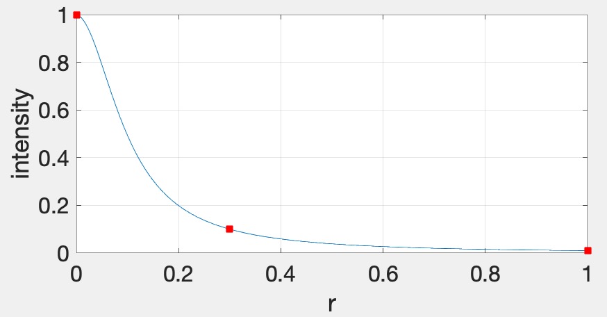
In this bonus task, we are going to increase the number of lights. First, because we are going to have many more lights, we are going to adjust the attenuation factor for this part of the assignment. Otherwise the scene will be over-exposed (too bright). Now, we want the light to fall off to \(10\)% of its strength at \(r=0.3\) and to \(1\)% at \(r=1.0\), which gives us \(A_0 = 1.0\), \(A_1 = 0.4286\), and \(A_2 = 98.5714\).
First, implement the naive approach, which uses a for-loop to go through all of the lights in the fragment shader. This is the ground truth, but this will become much too slow as the number of lights increases.
Therefore, we will now use tiled deferred rendering. The basic idea is to render a grid of small quads instead of one big quad that fills the screen. Each small quad will be rendered with only a subset of lights that affect the fragments within that quad. The images below show quads with black borders to visualize the grid. The various shades of red indicate the number of lights each quad is using.
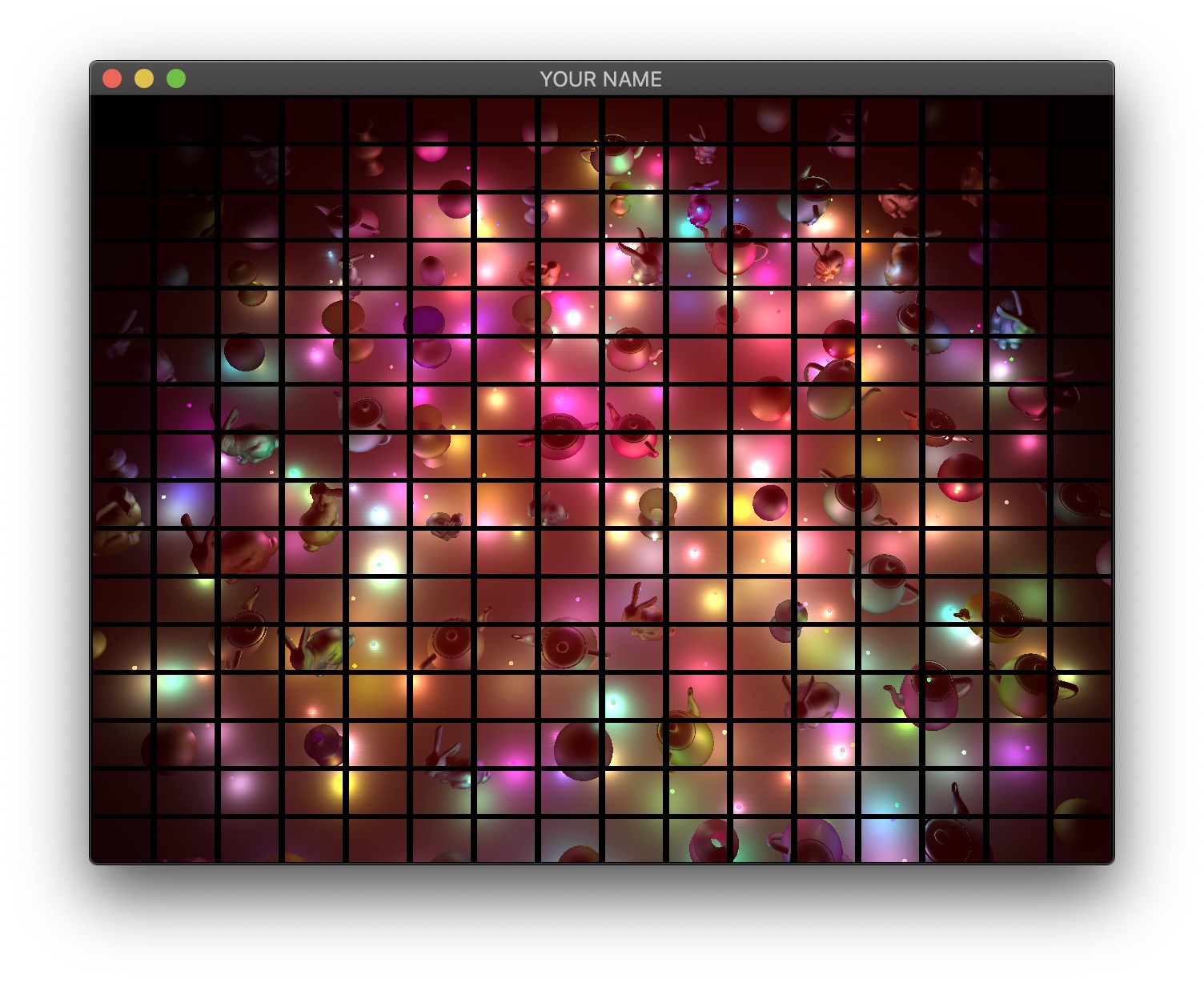
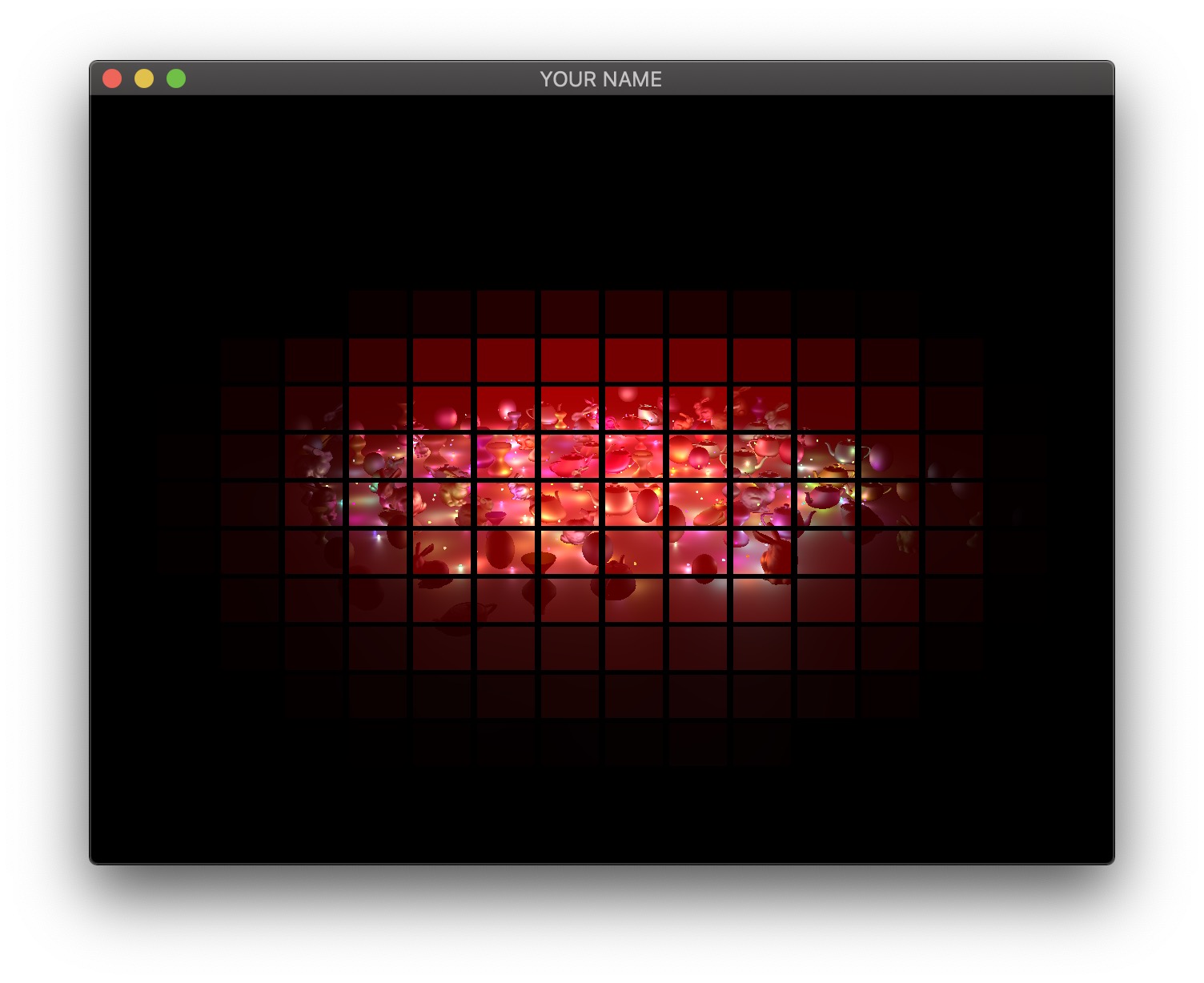
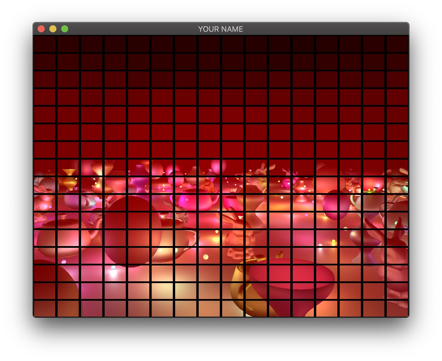
For each quad, we need to know which lights need to be included. To do this, we perform frustum-sphere intersection tests.
Each 2D quad on the screen is a 3D frustum in world space. The quad must be drawn somewhere between the near and far planes, and the size of the quad depends on exactly where it is drawn. In my implementation, I draw my quads half way between the near and far planes.
We will assume that each light has a sphere of influence of radius \(1\), since the intensity of each light falls to \(1\)% of its strength at distance \(r=1\).
The image above shows a view frustum originating at the camera and sandwiched between the near and far planes. The near and far distances are stored in the Camera class, if you’re using it. (Both \(n\) and \(f\) are negated because by convention these are defined to be positive distances away from the camera, but the actual near and far planes are along the negative Z axis in camera space.) The corners of the near plane are defined by left, right, bottom, and top (\(l\), \(r\), \(b\), and \(t\)). In the previous lab/assignment code, we have been using the field-of-view (fovy) and aspect arguments. To convert this to \((l,r,b,t)\), use the following:
l = -n * tan(fovy/2) * aspect;
r = -l;
b = -n * tan(fovy/2);
t = -b;
Once the overall view frustum for the whole window is derived, divide it into smaller frustums, one for each tile. For each small frustum, perform a frustum-sphere intersection test.
The image above shows a schematic of frustum-sphere intersections. For this assignment, each light sphere is of unit radius because of the attenuation factors chosen. For each frustum, check which light spheres intersect it, and then when rendering the quad for this frustum, only include the intersecting lights.
For the intersection tests, use the code by Daniel Holden. (You may need to pass arguments by reference to get good performance.) This piece of code requires you to specify the 6 planes of the frustum. I suggest using camera space to specify both the frustum and the spheres. To specify a frustum plane, you need to specify a point and a direction. For example, the near plane of the frustum can be defined by the point \((0,0,-n)\) and direction \((0,0,1)\), and the far plane can be defined by the point \((0,0,-f)\) and direction \((0,0,-1)\). The other 4 planes all share a common point (camera’s position in camera space), and so you can use the cross product to compute the plane directions. Don’t forget to normalize the result of the cross product.
Unfortunately, on many GPUs, dynamic branching can really slow down the shader. This means that even if we have a loop in the shader to calculate the contributions from only the lights intersecting the frustum, the GPU will not be able to speed up the code, since each quad will require a different subset of lights to be processed. The way we are going to get around this problem is to have multiple shaders that can handle increasing number of lights. For example, let’s say we have 200 lights in the scene. Then we create a shader that can handle \(0, 20, 40, \cdots, 200\) lights. If a quad has 5 lights, then we use the shader that can handle up to 20 lights, for 21 lights, use the shader with \(40\) lights, and so on. These shaders should have the following lines at the very top:
#version 120
const int LIGHTS_MAX = 20;
The shader expects the version string (#version 120) first. Otherwise, the shader will use the most basic profile, which is almost certainly not what you want. The second line above declares the constant that defines the number of lights this shader can handle. We want to create multiple shaders with different numbers in this line. Rather than creating these shaders as separate files, we can prepend some lines to the shader in the C++ code as follows (Program.cpp):
GLuint FS = glCreateShader(GL_FRAGMENT_SHADER);
const char *fshader = GLSL::textFileRead(fShaderName.c_str());
string fstr = "";
for(auto p : prepend) {
    fstr += p + "\n";
}
fstr += fshader;
const char *fstr_c = fstr.c_str();
glShaderSource(FS, 1, &fstr_c, NULL);
Here, prepend is a vector<string> that contains the lines to be added to the beginning of the shader.
Unfortunately, this might still be too slow because switching between GLSL programs can now become the bottleneck. It is reasonable to switch the program a few times during a render call, but changing 100 times would cause the parallelism to breakdown. Therefore, we sort the quads by the number of intersecting lights and then draw the quads in an increasing order in terms of the number of lights, switching the shader only when the number of lights crosses the next threshold. For example, let’s say the sorted quads have the following number of lights: \(0, 0, 1, 6, 10, 11, 18, 20, 21, \cdots\). Then we draw the first two quads using the ‘\(0\)’ shader, we draw the next six quads using the ‘\(20\)’ shader, etc. Figuring out how many shaders to use vs. cramming a lot of complexity into fewer shaders is a difficult balancing act that depends on the hardware, driver, and the OpenGL/GLSL code.
There are more optimizations that can be performed, but with the ones listed above, you should be able to get 200 lights at interactive rates for the default window size.
Total: 100 plus 25 bonus points
Failing to follow these points may decrease your “general execution” score. On Linux/Mac, make sure that your code compiles and runs by typing:
> mkdir build
> cd build
> cmake ..
> make
> ./A5 ../resources
If you’re on Windows, make sure that you can build your code using the same procedure as in Lab 0.
For this assignment, there should be only one argument. You can hard code all your input files (e.g., obj files) in the resources directory.
src/, resources/, CMakeLists.txt, and your readme file. The resources folder should contain the obj files and the glsl files.(*.~)(*.o)(.vs)(.git)UIN.zip (e.g., 12345678.zip).UIN/ (e.g. 12345678/).src/, CMakeLists.txt, etc..zip format (not .gz, .7z, .rar, etc.).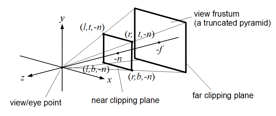
