In this lab, we’re going to use bilinear interpolation to deform a 2D mesh.
Please download the lab and go over the code.
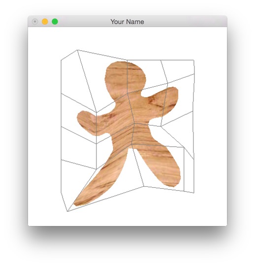
When you compile and run the source code, you should see a 2D figure
with a cage around it. The cage is draggable, but it won’t do anything
until you implement a couple of functions. You can change the grid size
by modifying grid->setSize() in the init()
function in main.cpp.
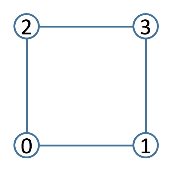
Set the grid size back to (2, 2) to get a 2 by 2 array
of grid points. Take a look at the function
ShapeCage::load(). The posBuf vector is being
filled with the data from the obj file. In the
ShapeCage::toLocal() function, which is called once at the
beginning of the program, this data is being passed through without
modification to the posLocalBuf vector, and in the
ShapeCage::toWorld() function, which is called every frame,
this data is being passed back to the posBuf vector. (Note
that posBuf is of size 3*nVerts, since it
comes from the input obj file, whereas posLocalBuf is of
size 2*nVerts, since only the 2D local coordinates are
stored.) This obviously does nothing when the grid moves. What you want
to do instead is to properly compute the local coordinates and then
compute the world coordinates from the local coordinates PLUS the new
grid configuration.
First, implement the ShapeCage::toLocal() function. For
now, since there is only one tile in the grid, you can ignore the
tileIndexBuf vector. (We will be using this later when we
increase the grid size.) For each vertex, posLocalBuf
should store where that vertex is with respect to the grid tile — i.e.,
its local coordinates. To get the four control points of the 0th tile
(currently our one-and-only tile), use the following:
vector<glm::vec2> cps = grid->getTileCPs(0);The returned vector cps contains the four control points
in this order:
To compute the local coordinates (u, v) of a vertex, get
the minimum and maximum (x, y) world coordinates of the
tile, and then use the following formula:
\[ u = \frac{x - x_\min}{x_\max - x_\min}, \qquad v = \frac{y - y_\min}{y_\max - y_\min}. \]
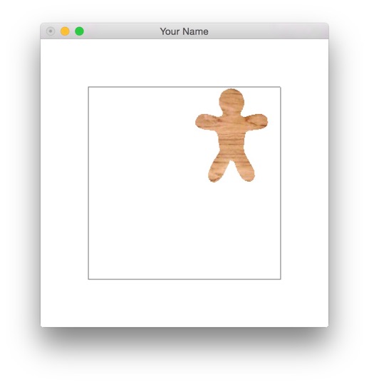
Once the local coordinates are computed properly, you should see the
character in the top right corner as shown. This is because the world
goes from (-1, -1) to (1, 1), and the local
coordinates are between 0 and 1. Once we implement
toWorld() in the next task, the character will fill the
whole tile again.
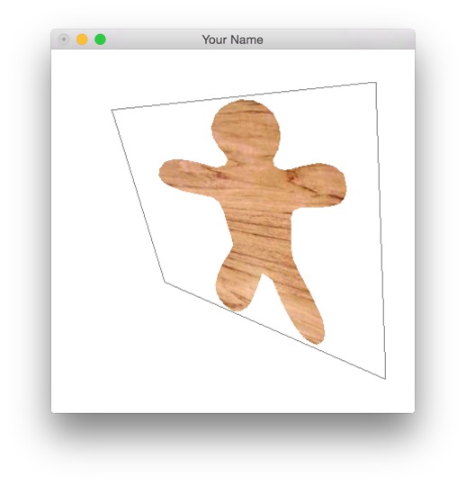
Now implement ShapeCage::toWorld(). In this function,
you should do the reverse of the transformation you applied above so
that the posBuf vector is filled with proper values. In
other words, for each vertex, apply the bilinear interpolation
function:
\[ \begin{aligned} & P_0(u) = (1 - u) P_{00} + u P_{01},\\ & P_1(u) = (1 - u) P_{10} + u P_{11},\\ & P(u,v) = (1 - v) P_0(u) + v P_1(u). \end{aligned} \]
You can get the four control points, \(P_{00}\) through \(P_{11}\) with the call to
grid->getTileCPs(0) as before. You should now be able to
move the character by moving the control points.
Increase the grid size to (5, 5). Since there are
multiple tiles now, the current code does not work. You need to change
both ShapeCage::toLocal() and
ShapeCage::toWorld().
In ShapeCage::toLocal(), you need to find which tile
each vertex belongs to by looping through all of the tiles. You can do
this with a double for-loop using the nrows and
ncols variables and a call to
grid->indexAt(row, col).
// Find which tile this vertex belongs to
for(int col = 0; col < ncols-1; ++col) {
for(int row = 0; row < nrows-1; ++row) {
// Get the four control points for corresponding to (row, col)
int tileIndex = grid->indexAt(row, col);
vector<glm::vec2> cps = grid->getTileCPs(tileIndex);
//
// DO SOME STUFF HERE
//
}
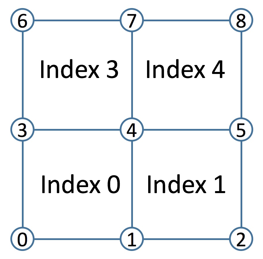
}Keep in mind that nrows and ncols are the
number of control points in the x and y directions, and so the number of
tiles is nrows-1 by ncols-1. The tile index
takes on the value of the control point at its lower left corner. For
example, if nrows=3 and ncols=3, then the tile
indices are:
In addition to the local coordinates, each vertex needs to store the
tile index. Store this in the tileIndexBuf vector. Note
that the length of this vector is nVerts, whereas the
length of posLocalBuf is 2*nVerts.
In ShapeCage::toWorld(), you should use both
tileIndexBuf and posLocalBuf to compute the
updated posBuf. First find the four control points you need
from the tile index of the vertex. Then use bilinear interpolation to
find the world coordinates of the vertex. You should now be able to move
the numerous control points to pose the character.
Now we’re going to implement bilinear interpolation on the GPU. You should add a keyboard hook to switch between the CPU and the GPU versions.
The ShapeCage::toLocal() function is going to remain the
same. However, you will no longer be needing the
ShapeCage::toWorld() function, since you will be doing this
transformation in the vertex shader. Think about what you need to do to
replace this function with GPU code.
Miscellaneous tips:
Before, you were passing posBuf to the vertex shader
as an attribute variable. Now you’ll be passing in
posLocalBuf instead. You need to transform these positions
from local to world in the vertex shader. Important:
posBuf is loaded from the obj file, and so it contains
(x,y,z) values for each position, but posBufLocal should
only contain (u,v) values. Therefore, the 2nd argument to
glVertexAttribPointer() should be 2, not 3.
In addition, you need to pass tileIndexBuf as an
attribute variable. You’ll need to use a float rather than an int
because some graphics cards do not support integer data types. In GLSL,
you can cast a float to int using a C++ style cast.
float bar;
...
int foo = int(bar);
You can hard code the grid size in the shader to
(5, 5).
You can pass in the 25 control points as a uniform parameter.
prog will have to be changed to match whatever variable
name you’re using.
// In the vertex shader:
uniform vec2 cps[25];
...
// In main.cpp:
glUniform2fv(prog->getUniform("cps"), 25, glm::value_ptr(grid->getAllCPs()[0]));
To access the four control points of the kth tile in the vertex shader:
vec2 cp00 = cps[k];
vec2 cp01 = cps[k + 1];
vec2 cp10 = cps[k + ncols];
vec2 cp11 = cps[k + ncols + 1];
You’ll need to add a new argument to
ShapeCage::draw() for the tile index attribute
array.