Please download the code for the lab and go over the code.
In this lab, we will alter an existing program in order to get started working with OpenGL, GLFW, and GLSL. Your goal is to be able to add two new colored triangles to the scene and to make one vertex of one triangle be repositioned based on a mouse click.
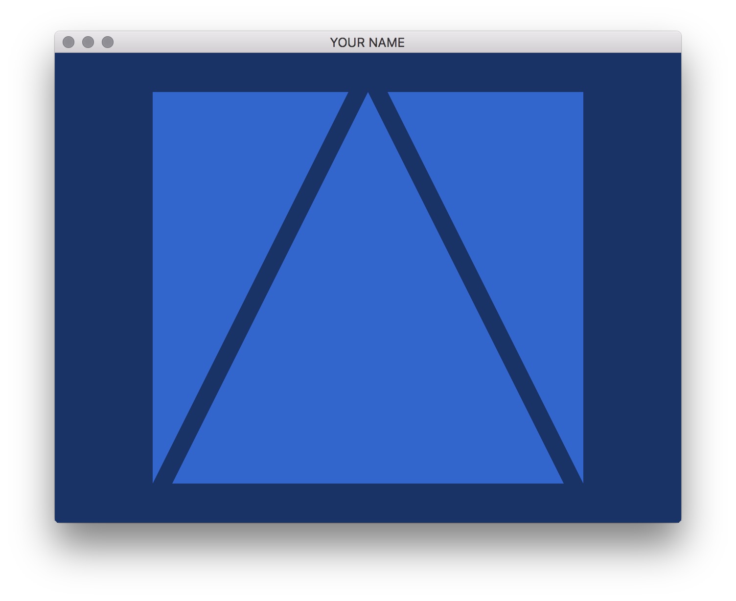
Modify the code to add two other triangles to the scene. You will do this by modifying main.cpp only. You will have to make modifications in init() as well as a small modification in render(). (Look for the hard-coded number 3.) Then modify the fragment shader to draw blue triangles, so it should look as follows:
Note that the colors is of type float, and so the R, G, and B values should be in the range \(0\) to \(1\).
Further modify the code to pass in a different color per vertex. For this, you will need to modify main.cpp, simple_vert.glsl, and simple_frag.glsl.
In the main C++ file, you’ll need to add the vertex color attributes. At the top of the file, add two more global variables named vertColAttrID and colBufID.
In the init() function, following the example of the vertex position attributes, complete the following for the vertex color attribute:
// Vertex position data
...
// Generate a buffer object
...
// Bind the buffer object to make it the currently active buffer
...
// Send the buffer data
...
// Unbind the buffer object
...
Similarly, the render() function should be modified to deal with the color attribute, just the way the position attribute is handled. The order is important:
// Tell OpenGL which GLSL program to use
...
// Pass in the current projection matrix
...
// Enable the position attribute
...
// Enable the color attribute
...
// Bind the position buffer object to make it the currently active buffer
...
// Set the pointer -- the data is already on the GPU
...
// Bind the color buffer object to make it the currently active buffer
...
// Set the pointer -- the data is already on the GPU
...
// Actually draw here
...
// Unbind the buffer object
...
// Disable the color attribute
...
// Disable the position attribute
...
// Unbind our GLSL program
...
In the two shaders, you’ll need to add a new varying parameter, which is an output of the vertex shader and an input of the fragment shader.
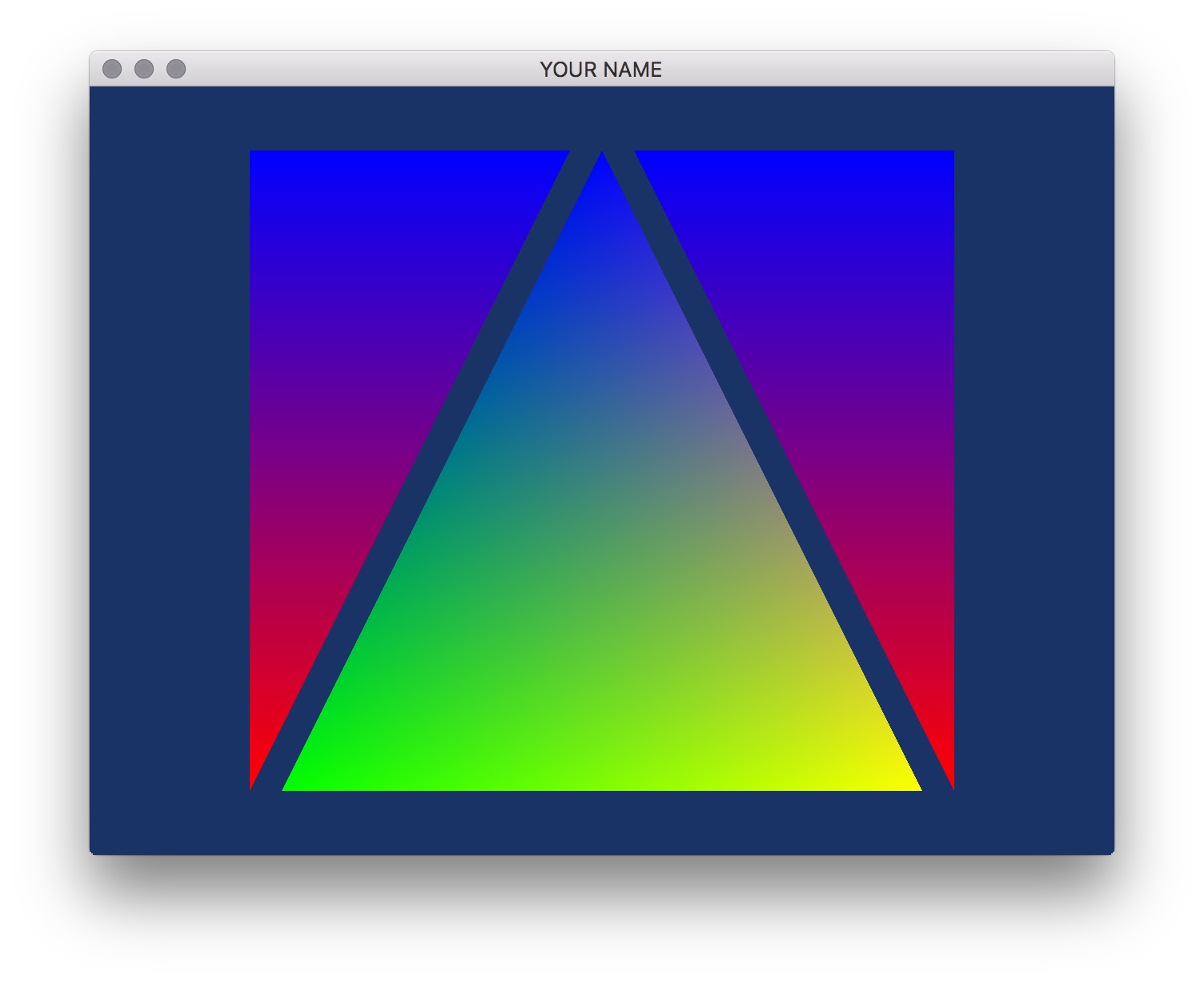
In the vertex shader, this parameter should simply pass through the incoming color. The fragment shader can then use this color to assign the final color of the fragment. This means that you’ll need to add a new attribute variable vertCol which is the vertex color attribute (like the vertex position attribute vertPos).
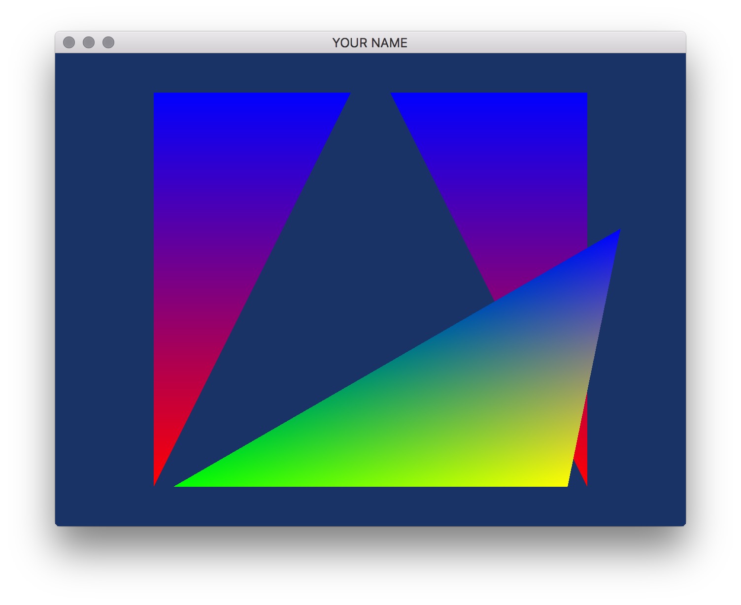
The result should look something like this:
Take a look at mouse_callback() in main.cpp. Using the variables xMinWorld, xMaxWorld, yMinWorld, yMaxWorld, width, and height, compute the world coordinates of the mouse cursor. Currently, the lab code sets this to be 0:
newPt[0] = 0;
newPt[1] = 0;
Replace these two lines with the result of your computation.
This transformation is very similar to how we transform world coordinates to image coordinates. Here, we want to go backwards: from image coordinates to world coordinates. The equations are:
\[ \begin{eqnarray} x_w &= s_x x_i + t_x,\\ y_w &= s_y y_i + t_y, \end{eqnarray} \]
where \((x_i, y_i)\) are the mouse coordinates (posX and posY in the code).
There are two slight differences from how we transformed from world to image in A1:
With these conditions, the parameters are:
\[ \begin{eqnarray} s_x &= \frac{\Delta x_w}{width},\\ s_y &= \frac{\Delta y_w}{height},\\ t_x &= \text{min}(x_w),\\ t_y &= \text{min}(y_w), \end{eqnarray} \]
where \(\Delta x_w\) and \(\Delta y_w\) are minimum and maximum of the visible world, and \(width\) and \(height\) are the size of the GLFW window.