Due Wednesday 4/26 at 11:59 pm. You must work individually.
In this assignment, you will be writing a ray tracer with the following features:
The skeleton code for Assignment 1 is a good starting point. Just like A1, this assignment does not use OpenGL and instead writes the result as an image file. You may also reuse any of your previous code from this course for this assignment. Even though you do not need OpenGL, you can still use the GLM library for matrices and vectors. Also, you do not need to load any obj files until Task 6.
The command line argument should be:
> ./A6 <SCENE> <IMAGE SIZE> <IMAGE FILENAME><SCENE>: Scene description number 1, 2, …, described below.<IMAGE SIZE>: Width/height of the resulting image, e.g., 1024<IMAGE FILENAME>: Output filename, e.g., output.png.Here’s the link to the 3D ray visualizer. Hitting the number key should produce the corresponding scene.
Set up the camera manually (using some trigonometry) with the following parameters:
(0, 0, 5)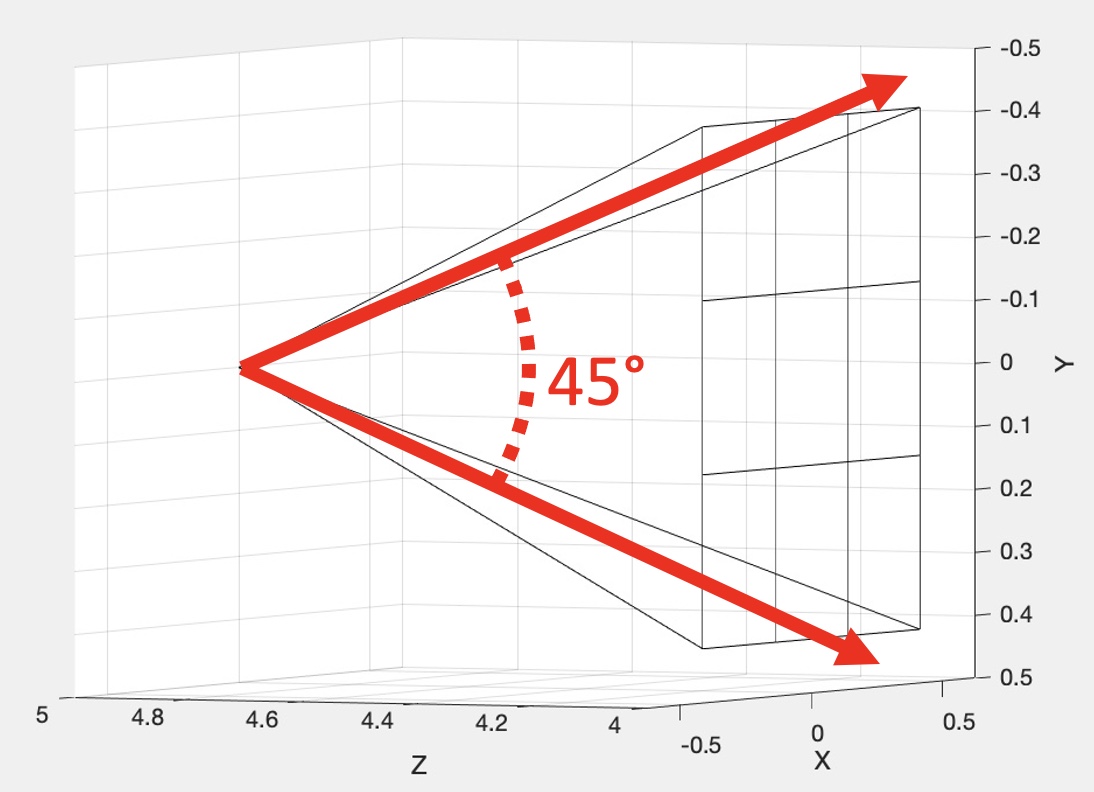
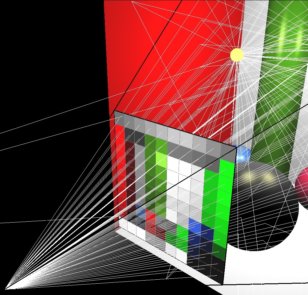
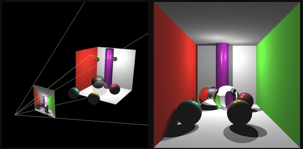
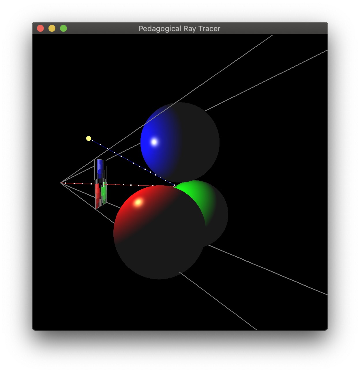
Imagine a virtual plane at Z=4.0 (i.e., one unit away from the camera, which is at Z=5.0). Our virtual rays will be starting at (0, 0, 5) and then will be going through the center of each pixel in the virtual plane. For example, in the center image, there are 9 rays, including one going straight out through the center of the middle pixel. The right image shows how these rays would look for a 10 by 10 image. (This was rendered with OpenGL for pedagogical purposes. Your code does not need to show the virtual scene in 3D.)
To start, write a function that can generate these rays given the camera specifications above, and the width/height of the output image from the commandline argument. With a 3x3 image, the 9 rays should have the following directions (each column is a unit direction vector):
    0.2572      0.0000     -0.2572      0.2662      0.0000     -0.2662      0.2572      0.0000     -0.2572
    0.2572      0.2662      0.2572      0.0000      0.0000      0.0000     -0.2572     -0.2662     -0.2572
   -0.9315     -0.9639     -0.9315     -0.9639     -1.0000     -0.9639     -0.9315     -0.9639     -0.9315
(Click here for a screenshot of the data in case your screen is too small.) Since the camera is not rotated, the middle ray’s direction is (0, 0, -1), straight ahead along the negative Z direction. Due to round-off errors, the numbers you get may be slightly different.
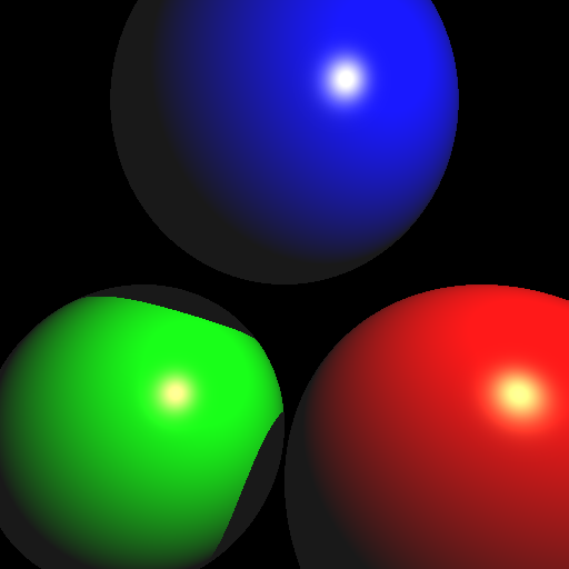
Your first scenes consist of three spheres and one light. Scene 1 is without shadows, and Scene 2 is with shadows. If you complete Scene 2, you do not need to keep the code for Scene 1. In other words, when the <SCENE> argument is set to 1, either of the images below will give you full points. When the <SCENE> argument is set to 2, only the right image below will give you full points.
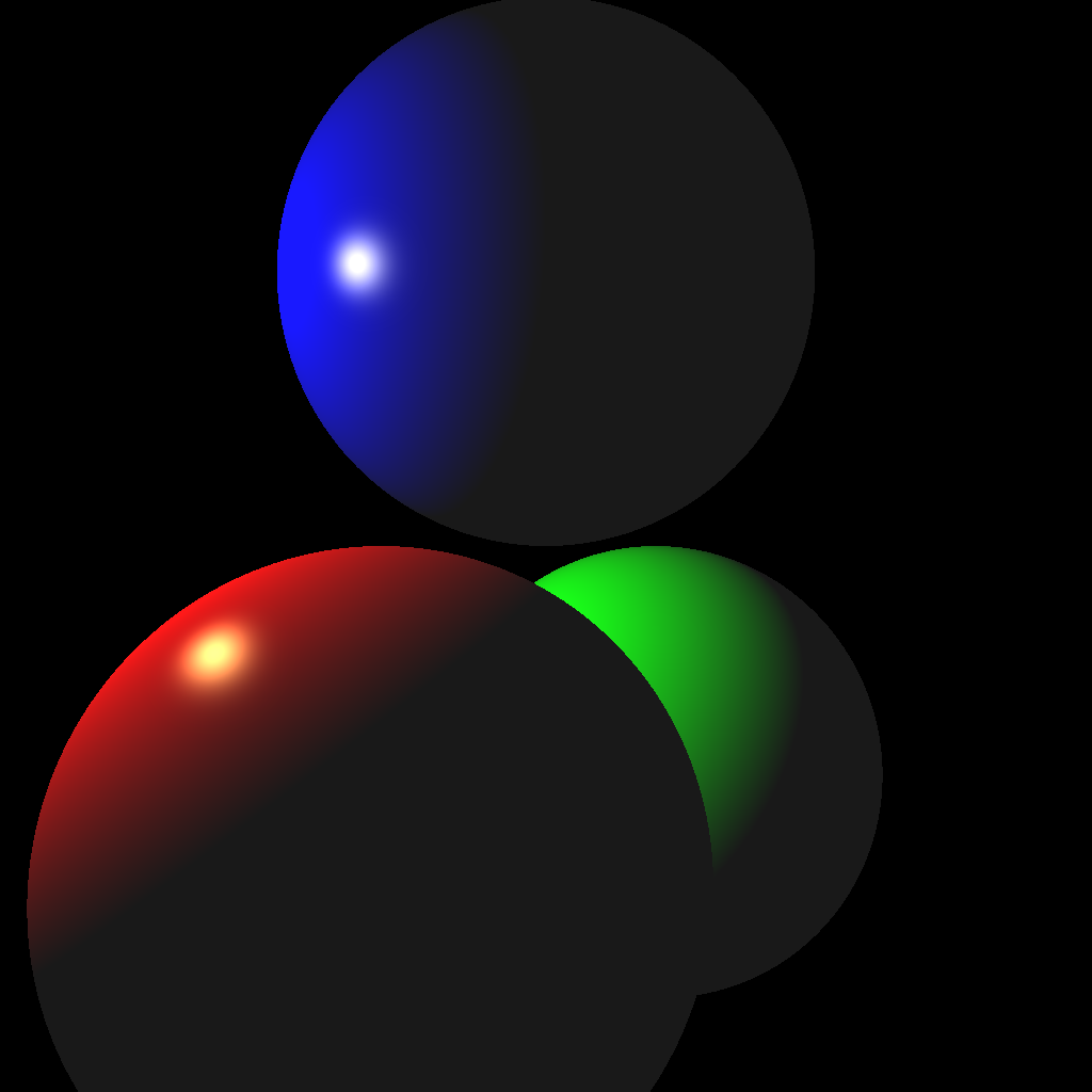
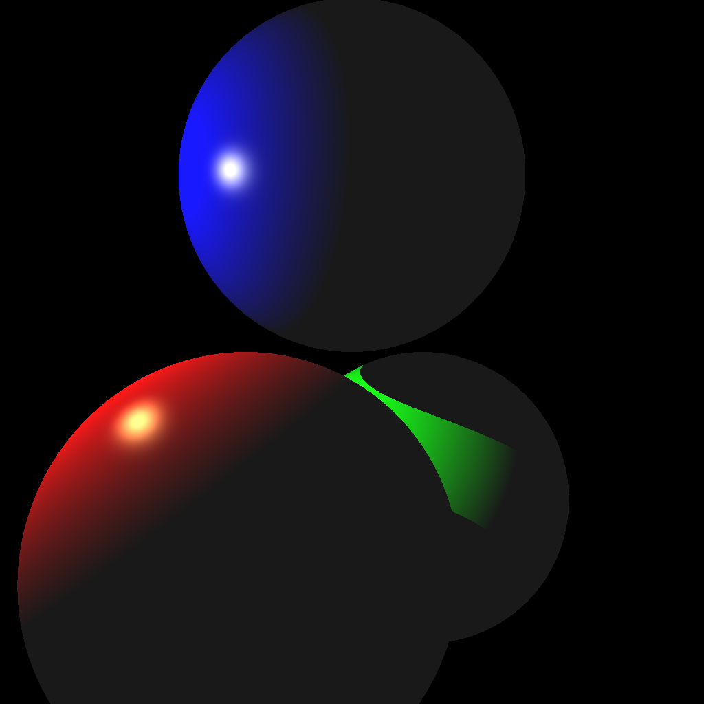
(Left) Without shadows. (Right) With shadows.
To create the scene, you can hard code the values in your code. (You may also use a parser if you prefer.) These values must be used when the command line argument <SCENE> is set to 1 or 2. Make sure to use exactly these values, since they will be used to test your code with an automatic script.
Light
(-2.0, 1.0, 1.0)1.0Red Sphere
(-0.5, -1.0, 1.0)(1.0, 1.0, 1.0)(1.0, 0.0, 0.0)(1.0, 1.0, 0.5)(0.1, 0.1, 0.1)100.0Green Sphere
(0.5, -1.0, -1.0)(1.0, 1.0, 1.0)(0.0, 1.0, 0.0)(1.0, 1.0, 0.5)(0.1, 0.1, 0.1)100.0Blue Sphere
(0.0, 1.0, 0.0)(1.0, 1.0, 1.0)(0.0, 0.0, 1.0)(1.0, 1.0, 0.5)(0.1, 0.1, 0.1)100.0I highly recommend writing test cases for the collision functions. For example, place a unit-radius sphere at the origin and shoot a ray from (0, 0, 5) with direction (0, 0, -1). The ray should hit the sphere at (0, 0, 1) and (0, 0, -1). Try other test cases, with a different radius and/or position, as well as different rays.
Once your intersection functions have been tested, you’re ready to start implementing a ray tracer. First, shoot just the primary view rays and not the shadow rays (Scene 1, left image above). Once you get the correct result, add the shadow rays (Scene 2, right image above).
The color should be computed using the Blinn-Phong equation we used in our previous assignments: \[ \vec{k}_a + \sum_i \vec{L}_i \odot \left( \vec{k}_d \max(0, \hat{n} \cdot \hat{l}_i) + \vec{k}_s \max(0, (\hat{n} \cdot \hat{h}_i)^s) \right). \] For Scene 2, if the shadow ray hits an object before reaching the light, the color contribution corresponding to that light should be set to zero.
Note: When setting pixel colors, cap each of the R, G, and B values to the range [0, 255].
Your code should be efficient enough to generate a 1024 by 1024 image without having to wait a long time. It should only take a few seconds at most, even on an older computer. If your code is slow, make sure you are not passing big STL vectors by value and that you are running your code in release mode. Excessively slow code will be penalized.
Also, use object-oriented design to organize your code. There should be a superclass that represents all shapes. The subclasses should implement specific intersection tests. For example, a subclass that represents an infinite plane should implement Task 2 from Lab 13, and another subclass that represents a sphere should implement Task 3 from Lab 13.
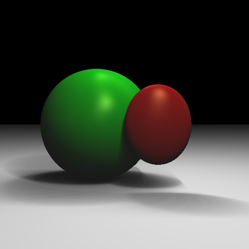
The next scene consists of one sphere, one ellipsoid, one infinite plane, and two lights.
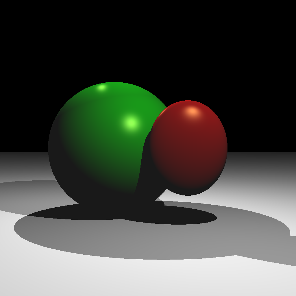
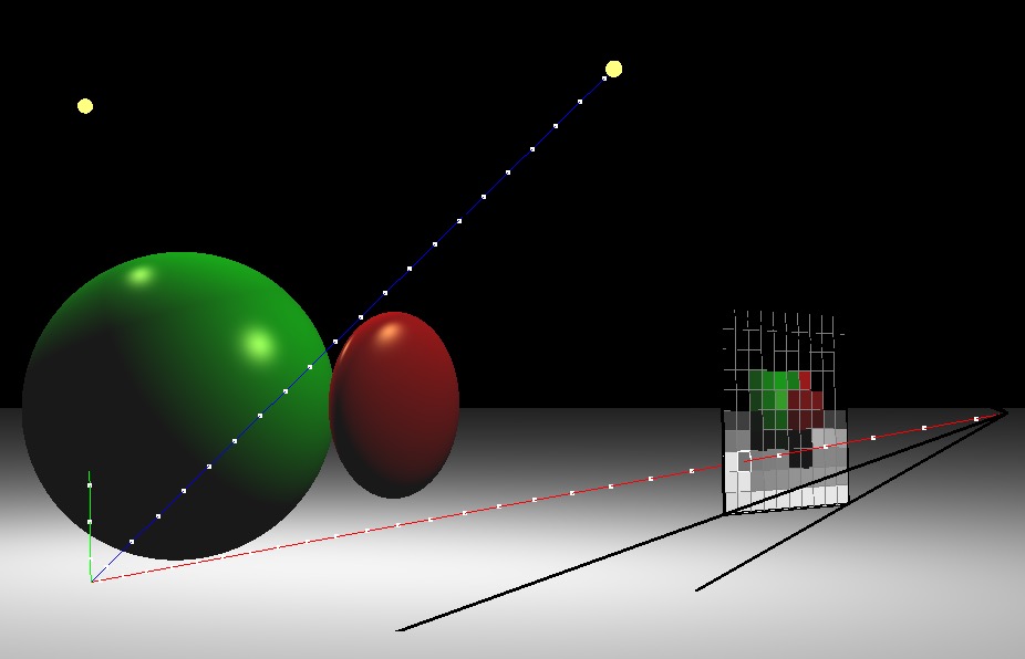
(Left) Ray traced scene. (Right) A rotated view showing one of the view rays. The blue shadow ray reaches the light, but the green shadow ray is blocked.
Light 1
(1.0, 2.0, 2.0)0.5Light 2
(-1.0, 2.0, -1.0)0.5Red Ellipsoid
(0.5, 0.0, 0.5)(0.5, 0.6, 0.2)(1.0, 0.0, 0.0)(1.0, 1.0, 0.5)(0.1, 0.1, 0.1)100.0Green Sphere
(-0.5, 0.0, -0.5)(1.0, 1.0, 1.0)(0.0, 1.0, 0.0)(1.0, 1.0, 0.5)(0.1, 0.1, 0.1)100.0Plane
(0.0, -1.0, 0.0)(1.0, 1.0, 1.0)(0.0, 0.0, 0.0)(0.1, 0.1, 0.1)0.0With two lights, you should be able to see areas that are occluded from both or just one light. Also note that the ellipsoid casts a shadow on the sphere.
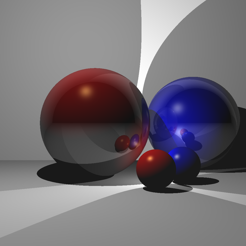
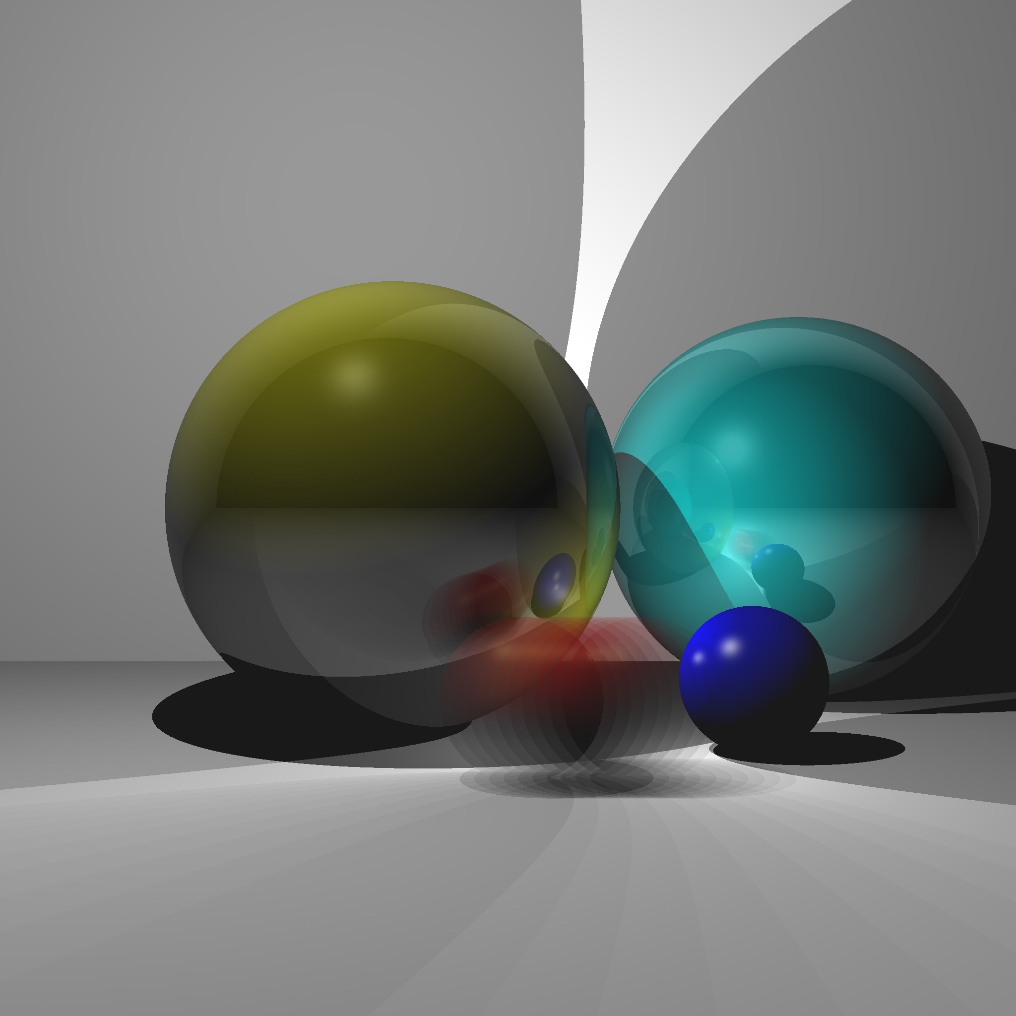
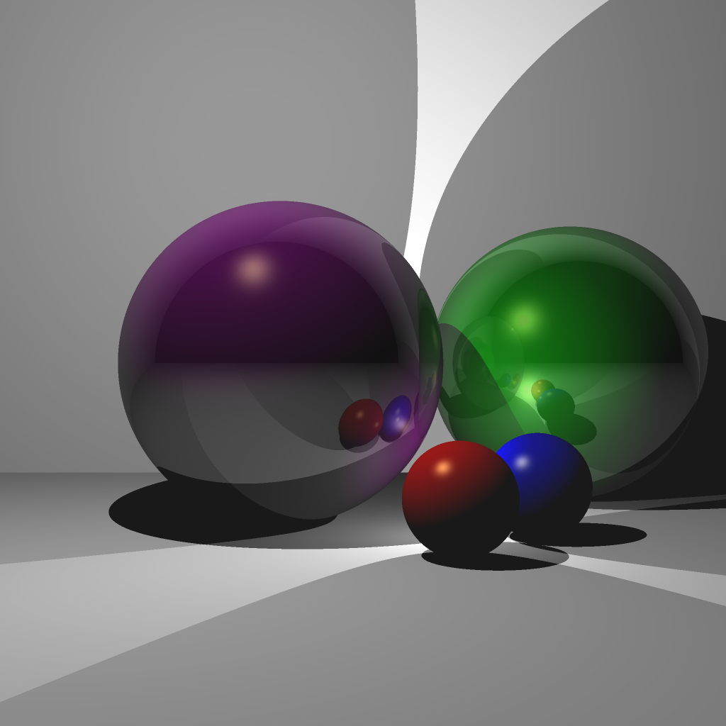
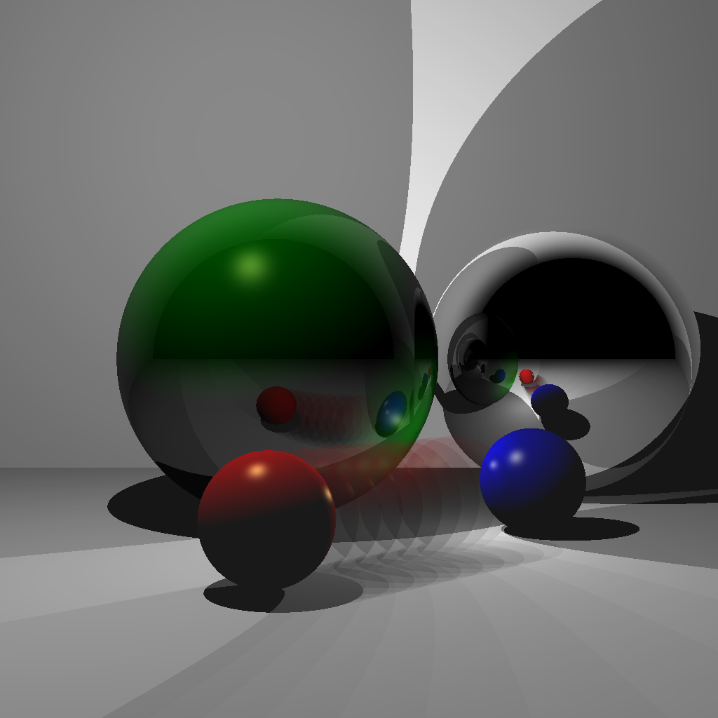
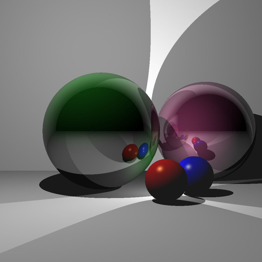
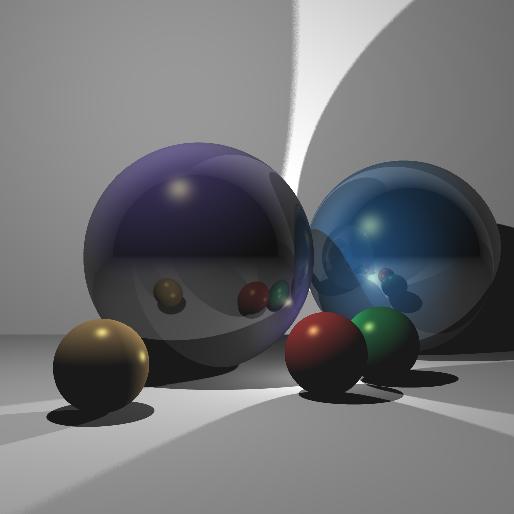
Your next scenes consist of two lights, two Phong spheres, two reflective spheres, and two infinite planes. Scene 4 is with a single reflection, and Scene 5 is with multiple (recursive) reflections. If you complete Scene 5, you do not need to keep the code for Scene 4. In other words, when the <SCENE> argument is set to 4, either of the images below will give you full points. When the <SCENE> argument is set to 5, only the right image below will give you full points.
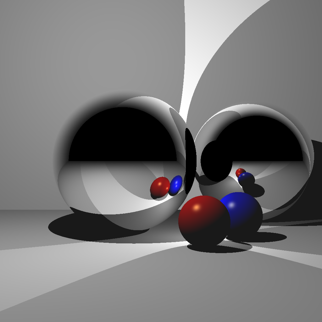
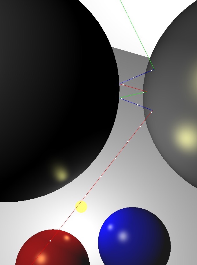
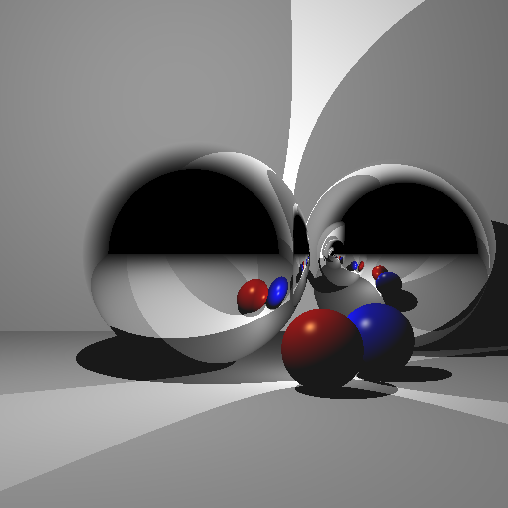
(Left) Rendered with a single bounce. Without enough recursion depth, the reflection of the other reflective sphere is not rendered. (Center) A closeup of multiple reflections. (Right) Rendered with multiple bounces.
Light 1
(-1.0, 2.0, 1.0)0.5Light 2
(0.5, -0.5, 0.0)0.5Red Sphere
(0.5, -0.7, 0.5)(0.3, 0.3, 0.3)(1.0, 0.0, 0.0)(1.0, 1.0, 0.5)(0.1, 0.1, 0.1)100.0Blue Sphere
(1.0, -0.7, 0.0)(0.3, 0.3, 0.3)(0.0, 0.0, 1.0)(1.0, 1.0, 0.5)(0.1, 0.1, 0.1)100.0Floor
(0.0, -1.0, 0.0)(1.0, 1.0, 1.0)(0.0, 0.0, 0.0)(0.1, 0.1, 0.1)0.0Back Wall
(0.0, 0.0, -3.0)(1.0, 1.0, 1.0)(0.0, 0.0, 0.0)(0.1, 0.1, 0.1)0.0Reflective Sphere 1
(-0.5, 0.0, -0.5)(1.0, 1.0, 1.0)Reflective Sphere 2
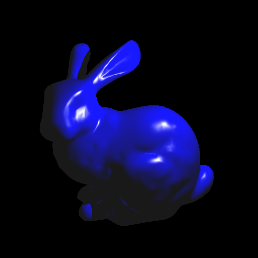
(1.5, 0.0, -1.5)(1.0, 1.0, 1.0)For these scenes, import an obj mesh. Scene 6 is without model transformation, and Scene 7 is with model transformation. Once you finish Scene 7, you should set up your code so that Scene 6 uses the identity transform.
For triangle-ray tests, use the optimized code by Thomas Akenine-Moller. Some hints for this piece of code:
1 or 0 depending on whether there was a hit.orig and dir are the ray origin and direction, respectively.vert0, vert1, and vert2 are the three vertex positions of the triangle.t is the distance along the ray where the hit occurred.
t > 0 to deal with collisions happening behind the ray.u and v are the barycentric coordinates of the triangle where the hit occurred.
u corresponds to vert1, and v corresponds to vert2.Without any optimizations, using the bunny mesh will take a very long time to render, since each ray will need to be tested against every single triangle. Add a simple optimization by putting a bounding sphere around the bunny and testing the ray against the sphere first. If the ray does not hit the sphere, you do not need to test against any of the triangles. It should not take more than a minute to render a bunny with a single light at 512x512 resolution. Make sure to run your code in release mode. We will be testing your submission with the bunny mesh.
There should be a single light in the scene, and the material should be the same as the blue sphere from the previous task.
Light
(-1.0, 1.0, 1.0)1.0Material
(0.0, 0.0, 1.0)(1.0, 1.0, 0.5)(0.1, 0.1, 0.1)100.0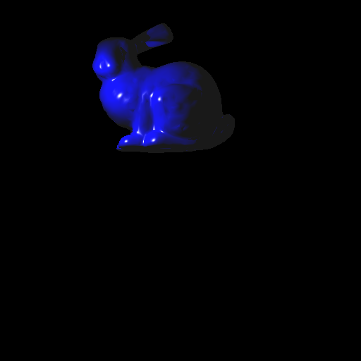

Now add the ability to transform the obj mesh. To do this, you need to transform the ray into local coordinates, perform collision detection, and then transform the result back to world coordinates. Let \(E\) be the 4x4 transformation matrix of the obj mesh. Then:
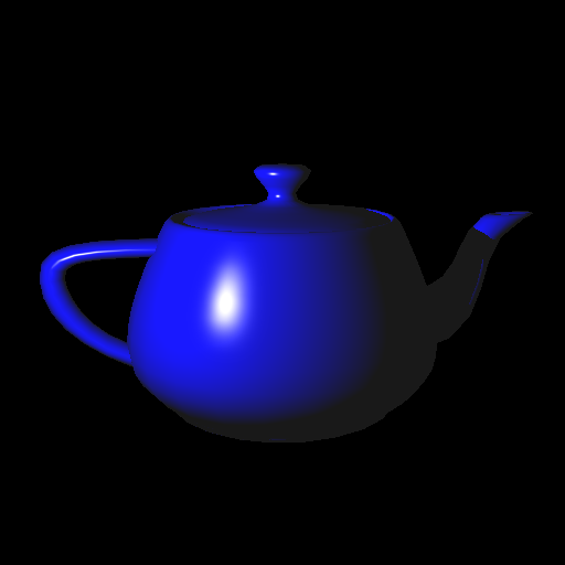
For Task 7, there should be a single light in the scene:
(1.0, 1.0, 2.0)1.0We will be testing your submission with the bunny mesh with the following model transform:
E =

    1.5000         0         0    0.3000
         0    1.4095   -0.5130   -1.5000
         0    0.5130    1.4095         0
         0         0         0    1.0000
This transformation matrix can also be constructed as the product E = T * R * S, where
T is a translation by (0.3, -1.5, 0.0).R is a rotation about the X-axis by \(20\) degrees.S is a uniform scale by 1.5.Implement a camera that can be translated/rotated arbitrarily in the world and whose field of view can be modified. Use the same setup as Scene 1 but from a different camera location/orientation. The camera should be placed at (-3,0,0) looking along the positive X axis, with a field of view of 60 degrees. The left image is the 3D view from the original viewpoint of Scene 1, and the right image is the resulting ray traced image.
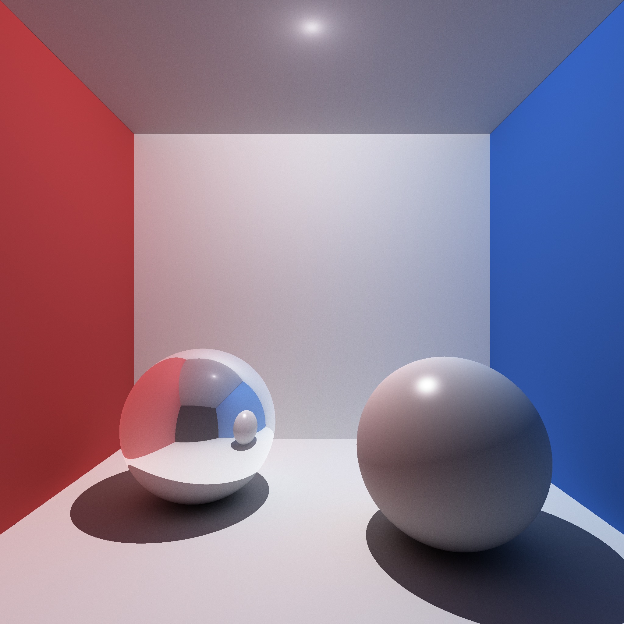
Once you finish the base assignment, you can earn up to 20 bonus points by implementing the following features (in no particular order):
Please use Scene 0 or 9 for the bonus scenes. The other scene numbers must work as if no bonus were implemented.
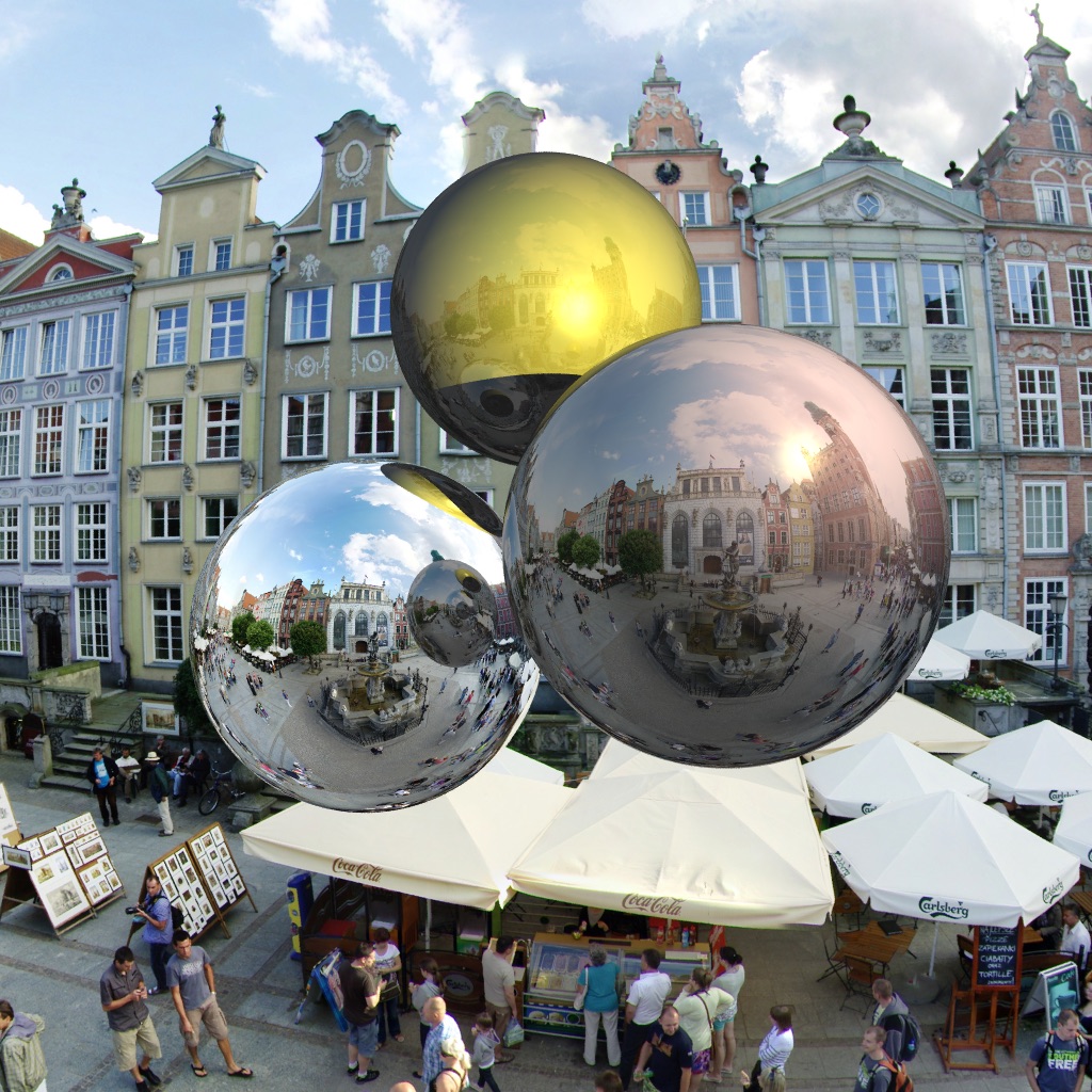
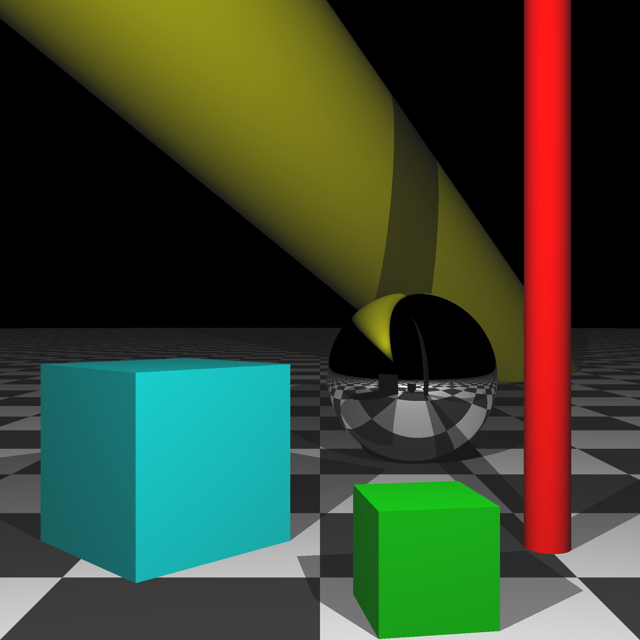
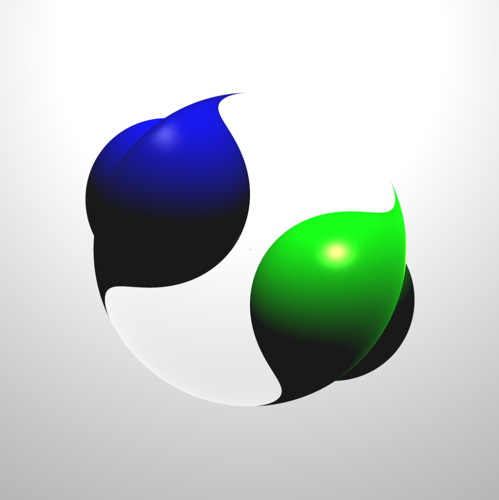
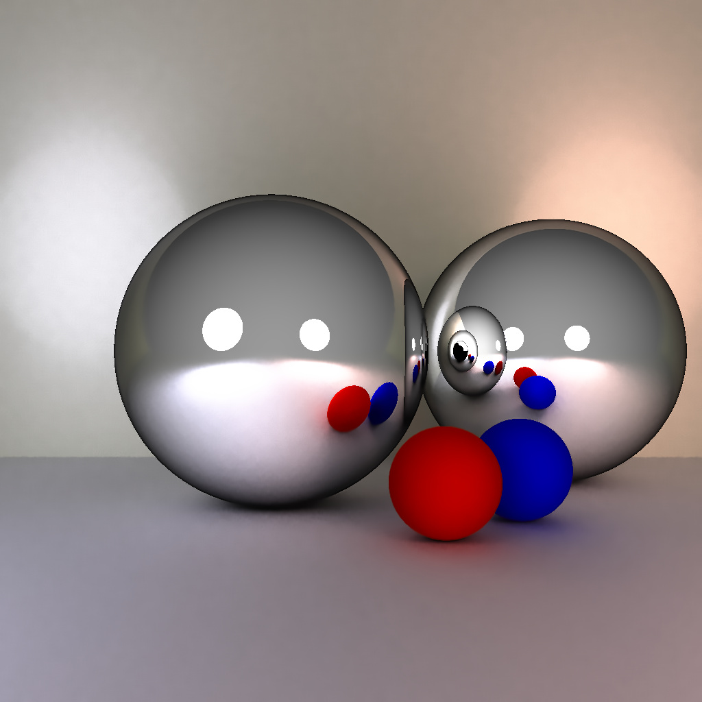
(Left) Blend between reflection and Blinn-Phong [Nkemdi Anyiam 2021]. (Center) Spherical environment mapping [Rebecca McFadden 2021]. (Right) Area lights [Michael Stewart 2021].
(Left) Monte-Carlo path tracing [Jonah Taylor 2021]. (Center) Reflection/Blinn-Phong and motion blur [Michael Hu 2022]. (Right) Reflection/Blinn-Phong and anti-aliasing [Senhe Hao 2022].
(Left) Reflection/Blinn-Phong and motion blur [Samantha Hallam 2022]. (Center) Reflection/Blinn-Phong [Kunal Gupta 2022]. (Right) Boxes, cylinders, and texturing [Peter Castelein 2022].
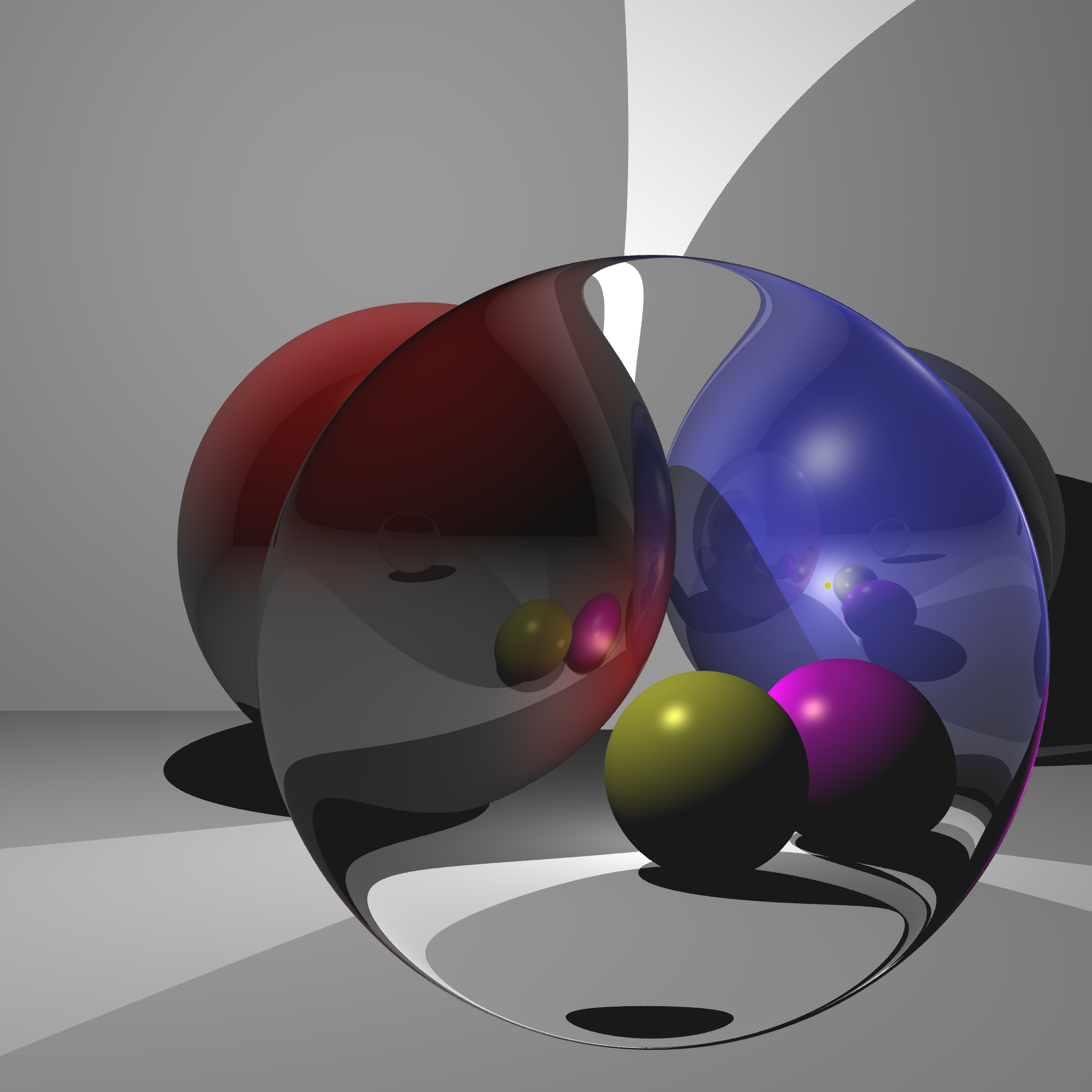
(Left) Refraction [Raul Escobar 2022]. (Center) Ambient occlusion, soft shadows, anti-aliasing, and refraction [Preston Barnett 2023]. (Right) Path tracing [Kevin Champagne 2023].
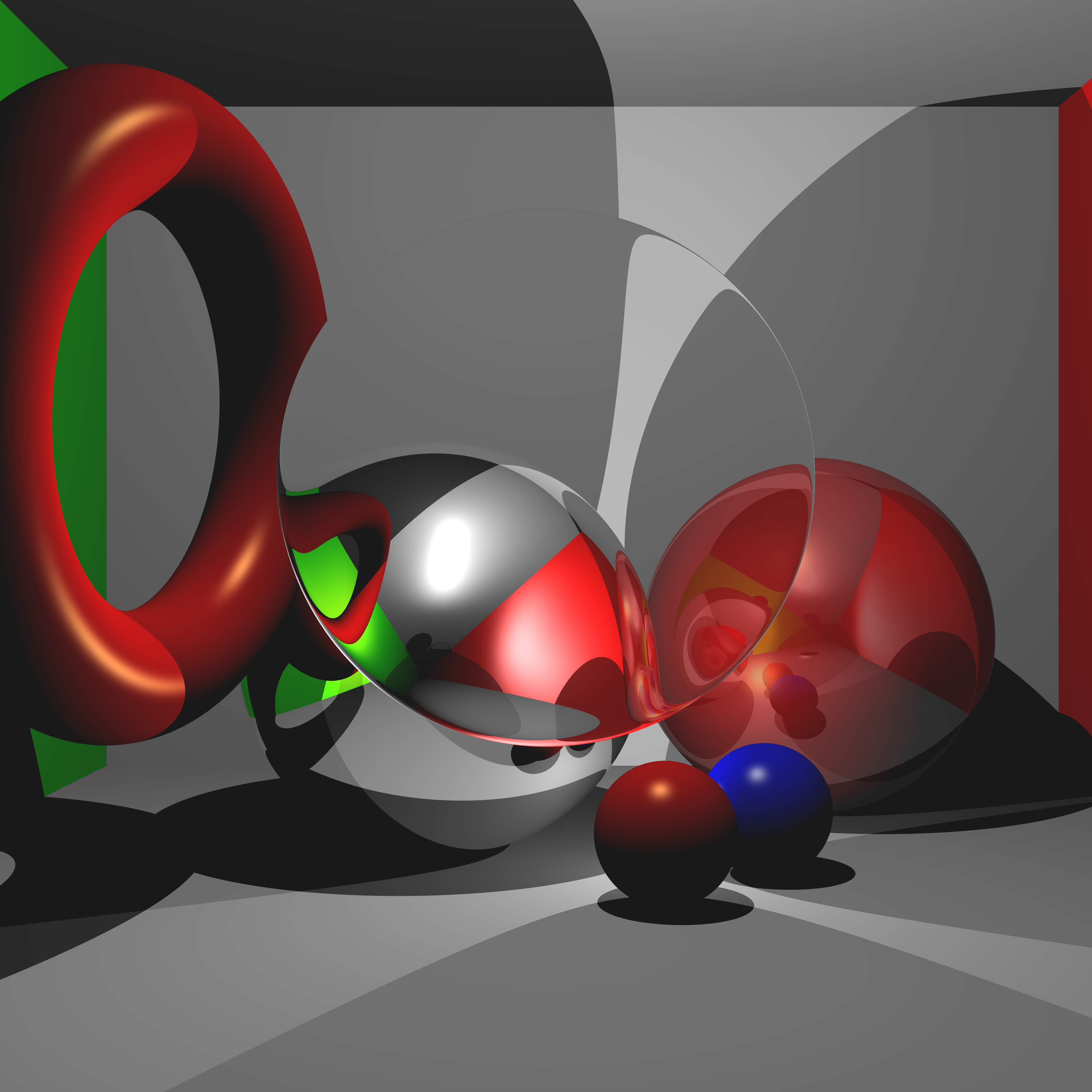
(Left) Reflection/Blinn-Phong and motion blur [Octavio Almanza 2023]. (Center) Torus, refraction, and anti-aliasing [Kiran Bhattarai 2023]. (Right) Reflection/Blinn-Phong, refraction, and anti-aliasing [Ibrahim Ozgel 2023].
Reflection/Blinn-Phong, soft shadows, surface roughness, and anti-aliasing [Lucy Zhang 2023].
In each task, you must use object-oriented design to obtain full points.
Total: 100 plus 20 bonus points.
For honors students: you must complete at least 10 bonus points. (Otherwise, you will receive a \(0\) on this assignment.) Like all other students, you can still finish Scene 8 and earn up to 20 bonus points to end up with 120 total points.
Failing to follow these points may decrease your final score. On Linux/Mac, make sure that your code compiles and runs by typing:
> mkdir build
> cd build
> cmake ..
> make
> ./A6 <SCENE> <IMAGE SIZE> <IMAGE FILENAME>
If you’re on Windows, make sure that you can build your code using the same procedure as in Lab -1.
src/, resources/, CMakeLists.txt, and your readme file. The resources folder should contain the obj files (if necessary).(*.~)(*.o)(.vs)(.git)UIN.zip (e.g., 12345678.zip).UIN/ (e.g. 12345678/).src/, CMakeLists.txt, etc..zip format (not .gz, .7z, .rar, etc.).