Due Tuesday 3/29 Wednesday 3/30 at 11:59 pm. You must work individually.
To become proficient with the use of 3D transforms and projections in OpenGL and to continue working with Blinn-Phong shading. Specifically, you will:
There is no base code provided for this assignment. Please start with your previous lab/assignment code. Please come see the instructor or the TA if you need help completing your previous assignment.
Write some code so that you can add multiple objects to the world. Each object should have some member variables so that you can easily translate/rotate/scale/shear the object in the world. (Remember that to transform the normals properly, you’ll need to send the inverse transpose matrix as a parameter to the shader if you include shear or non-uniform scales.) For this initial stage, since we’re using the default camera from previous assignments/labs, the objects that you add to the world may have to be scaled small so that they’re visible from the camera. Once you implement freelook later in this assignment, you may need to re-transform these objects to distribute them in the world the way you want.
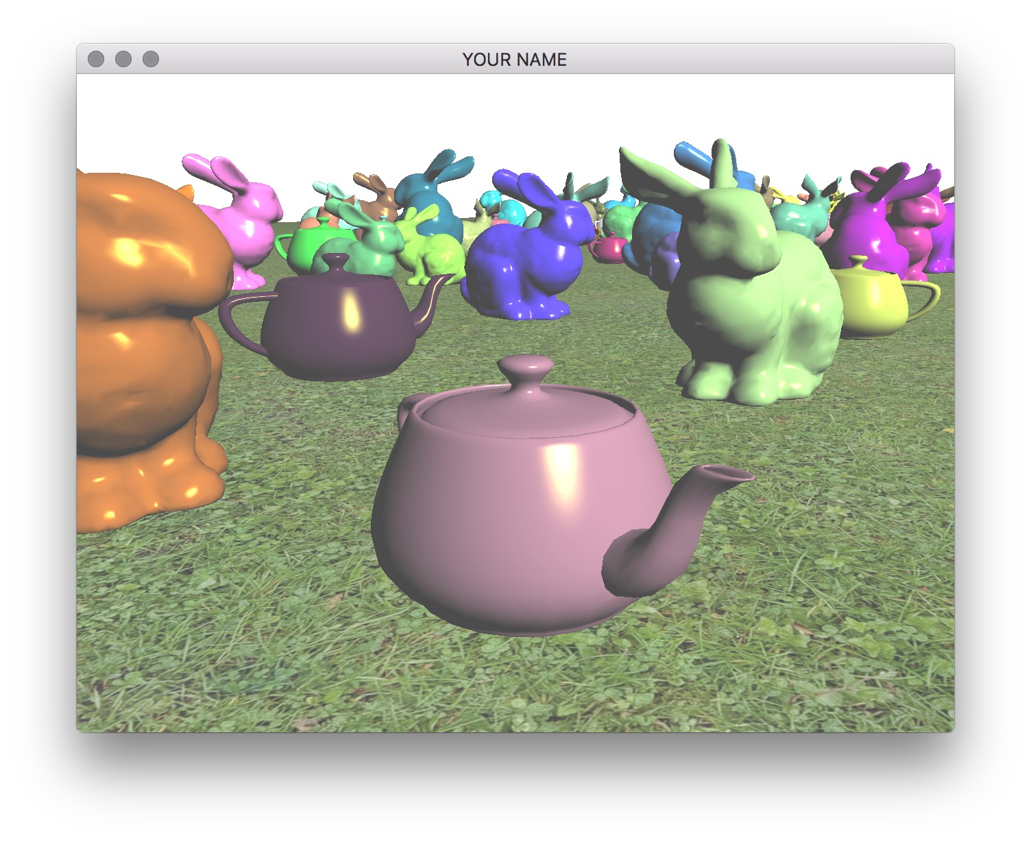
You should include at least two types of shapes. For example, here I’m using the bunny and the teapot shapes. You can use any model, but please try to keep the file sizes reasonable. If you download a model, please put a citation in your readme. Note that some OBJ files may not come with normals or texture coordinates.
You should add at least 100 things in the scene and a ground plane. These objects should be distributed (roughly) equally on the ground plane. (E.g., do not put them in a straight line.) It is important to load each OBJ file just once, even if you are going to draw that shape multiple times. One good way to do this is to create a new class that has a pointer/reference to a Shape instance. Each object must be translated so that the bottom of the object touches the ground. To do this, you will need the most negative Y coordinate of the mesh.
Use your Blinn-Phong shader from your previous assignment to shade the models. The objects should be assigned random colors. Unlike the last assignment, the light position should be fixed in the world. This means that the light position is no longer a constant in camera space. You need to choose a world space position for the light and then multiply this position by the view matrix (modelview matrix before adding any modeling transforms) to transform the light position into camera space. The camera-space light position should then be sent to the fragment shader as a uniform variable.
Finally, draw a sphere (the sun) where the light is. The lighting on the objects in the scene should match this location of the light source. In the image below, note how the left side of the green bunny is correctly lit by the light in the upper left corner of the image.
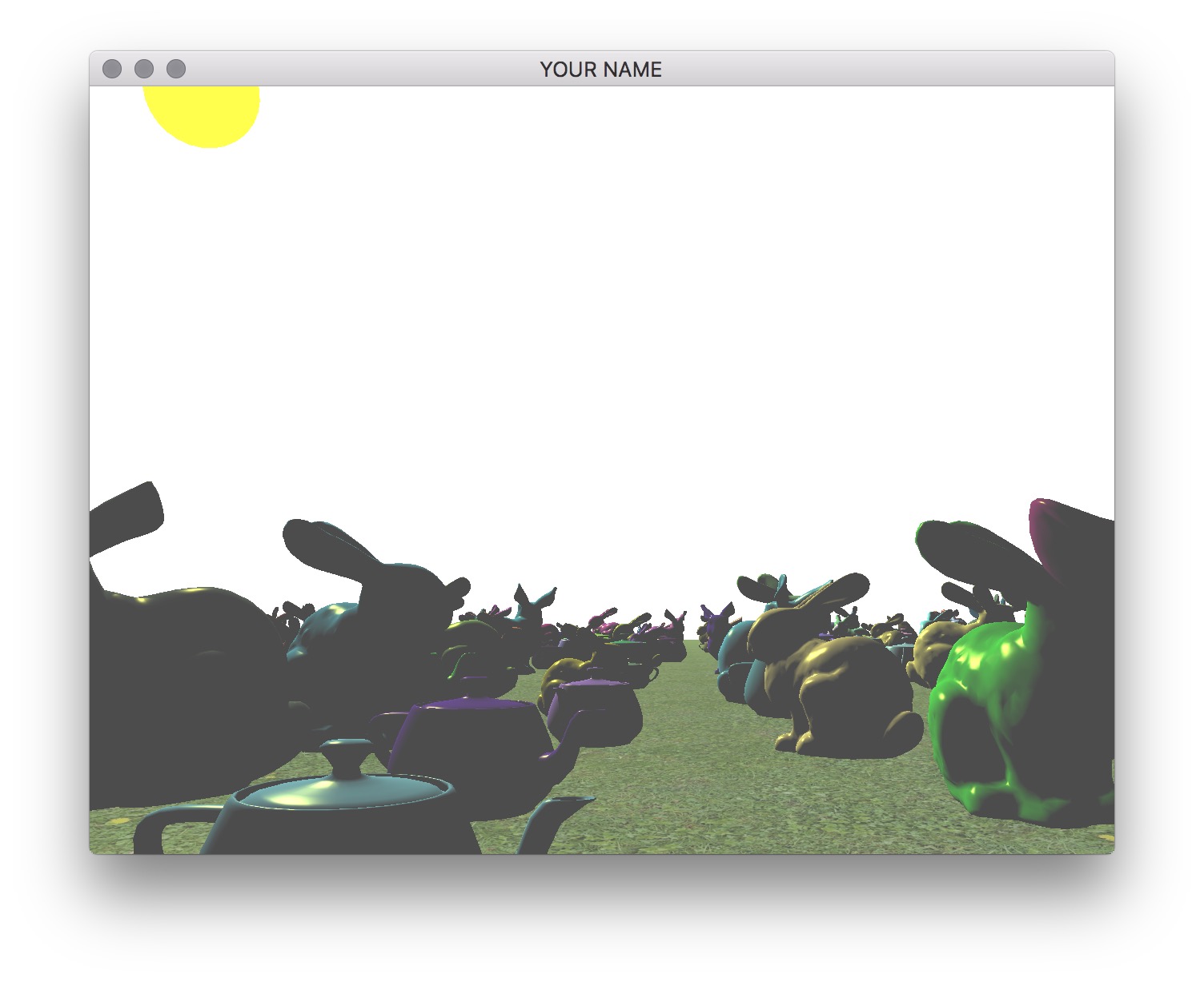
The shader for drawing the light can be the same Blinn-Phong shader as for the other models. You can set the ambient color to be the color of the sun, and diffuse and specular colors to be zero.
Now replace the Camera class with your own class that implements freelook. You can reuse the applyProjectionMatrix() method, but you’ll need to modify the applyViewMatrix() method. To implement freelook, the new camera class needs to keep track of its position, yaw, and pitch. From these three quantities, you need to come up with the correct arguments for the glm::lookAt() function.
The general setup of your code should be as follows:
render() method in main.cpp, the first matrix in the modelview matrix stack should be filled by the applyViewMatrix() method of your new freelook camera class. In the applyViewMatrix() method, you should use the glm::lookAt() method to create this view matrix.The eye, target, and up arguments of the lookAt() function are:
eye: camera positiontarget: camera position + “forward” directionup: the Y vector, \((0, 1, 0)\), (assuming Y-up)Position
I suggest fixing yaw and pitch first so that you can get basic translation correct with no rotation. The initial position of the camera should incorporate the height of the camera off of the ground.
Add keyboard hooks for WASD for translation:
w: move forwarda: move lefts: move backwardd: move rightPressing these keys should update the translation of the camera.
For now, the “forward” direction can be set to the negative Z direction, which is the default camera direction in OpenGL. When the w key is pressed, the camera should move along this “forward” direction. In the applyViewMatrix() method of your camera class, feed this new translation value into the lookAt() function.
Yaw
Now add yaw to your freelook camera, which allows you to look right and left. The X-motion of the mouse should be tied to the yaw angle of the camera. Look at the previous camera class from the labs to see how mouse inputs are handled.
The “forward” direction should be computed based on the yaw angle. If the ground is on the \(y=0\) plane, then the forward direction is
\[ \vec{f} = \begin{pmatrix} \sin(\theta)\\ 0\\ \cos(\theta) \end{pmatrix}, \]
where \(\theta\) is the yaw angle. The w key should now move the camera along this new “forward” direction, rather than the negative Z direction. The “left” direction (or the “right” direction) can be computed using the cross product: “right” = “forward” cross “up”. If this is working properly, pressing the w key should move the camera forward, and pressing the d key should move the camera to the right, no matter which way it is facing with respect to the world.
Pitch
Finally, add the pitch angle, which allows you to look up and down. The Y-motion of the mouse should be tied to the pitch angle of the camera. Unlike the yaw angle, the pitch angle should be capped at some reasonable limits (e.g., -60 to +60 degrees). The pitch angle should change the “target” argument of the lookAt() method, since it changes the “forward” direction that the camera is looking at. In other words, when computing the “target” argument, the “forward” vector should have a Y component that depends on the pitch angle. However, the pitch angle should not change the direction of motion. Even if the camera is looking up or down, pressing w should not change the height of the camera. (The camera should not lift off of or go into the ground.)
Zoom
Add zooming functionality to the camera using the z/Z keys (zoom in and zoom out). Pressing these keys should change the field of view in Y (FOVY) of the camera. The field of view should be capped between \(4\) degrees and \(114\) degrees. These correspond to roughly \(600\) mm and \(14\) mm lenses for full-frame cameras.
Depending on which skeleton code you start from, the z key may already be mapped to enable wireframe display mode. If so, delete or comment out the code to change the glPolygonMode(...) in the render function.
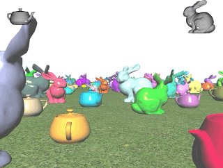
Transform the objects over time using the glfwGetTime() function. (See the image below.)
Add a head-up display (HUD) that shows objects (e.g., bunnies) on the two upper corners of the screen.
Now we’re going to add a “top-down” orthographic view. As the camera moves around the world, this top-down view should show where the camera is and which direction it is pointing.
Add Another Viewport
First, add a second viewport to the lower left of the screen. This viewport should be activated/deactivated by pressing the t key. Within this viewport, draw the scene objects (models, ground, sun) again but with different projection and view matrices. The pseudocode for the render() function is as follows:
// Main viewport (your current code should be doing something like this already)
glViewport(0, 0, width, height);
P->pushMatrix();
MV->pushMatrix();
APPLY PROJECTION MATRIX FOR MAIN VIEWPORT
APPLY VIEW MATRIX FOR MAIN VIEWPORT
DRAW SCENE
MV->popMatrix();
P->popMatrix();

// Top-down viewport (new code for this task)
if top-down view activated
    double s = 0.5;
    glViewport(0, 0, s*width, s*height);
    glEnable(GL_SCISSOR_TEST);
    glScissor(0, 0, s*width, s*height);
    glClear(GL_COLOR_BUFFER_BIT | GL_DEPTH_BUFFER_BIT);
    glDisable(GL_SCISSOR_TEST);
    P->pushMatrix();
    MV->pushMatrix();
    APPLY PROJECTION MATRIX FOR TOP-DOWN VIEWPORT
    APPLY VIEW MATRIX FOR TOP-DOWN VIEWPORT
    DRAW SCENE
    MV->popMatrix();
    P->popMatrix();
end
Some notes about this pseudocode:
glfwGetFramebufferSize(window, &width, &height);.P->multMatrix(glm::ortho(...)) (see the documentation on the ortho function here).MV->translate(...) and MV->rotate(...). By default, the camera is at the origin, looking down the negative Z-axis. For this viewport, you need the camera’s origin to be above the X-Z plane, looking down the negative Y-axis.Draw the Frustum
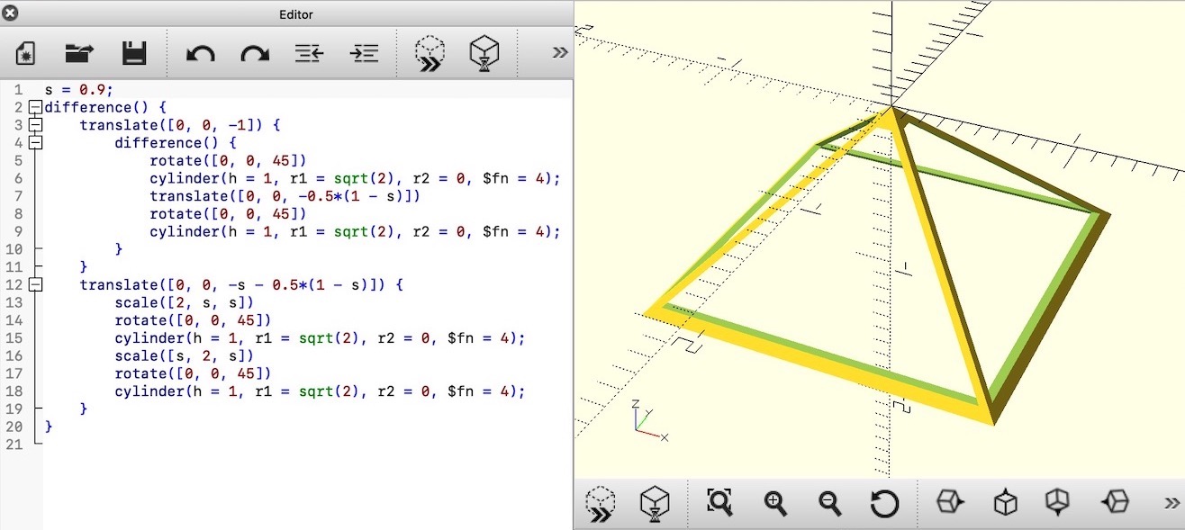
Next, draw the view frustum in the top-down view. To create the mesh for the frustum, we’ll be using OpenSCAD. Download, install, and start the application, and then copy the following code into the editor.
s = 0.9;
difference() {
    translate([0, 0, -1]) {
        difference() {
            rotate([0, 0, 45])
            cylinder(h = 1, r1 = sqrt(2), r2 = 0, $fn = 4);
            translate([0, 0, -0.5*(1 - s)])
            rotate([0, 0, 45])
            cylinder(h = 1, r1 = sqrt(2), r2 = 0, $fn = 4);
        }
    }
    translate([0, 0, -s - 0.5*(1 - s)]) {
        scale([2, s, s])
        rotate([0, 0, 45])
        cylinder(h = 1, r1 = sqrt(2), r2 = 0, $fn = 4);
        scale([s, 2, s])
        rotate([0, 0, 45])
        cylinder(h = 1, r1 = sqrt(2), r2 = 0, $fn = 4);
    }
}
Then follow these steps in OpenSCAD:
Open the STL file in MeshLab. Uncheck the option to ‘Unify Duplicated Vertices in STL files’ because we want to retain the hard corners. Then:
The left image below shows the exported mesh.
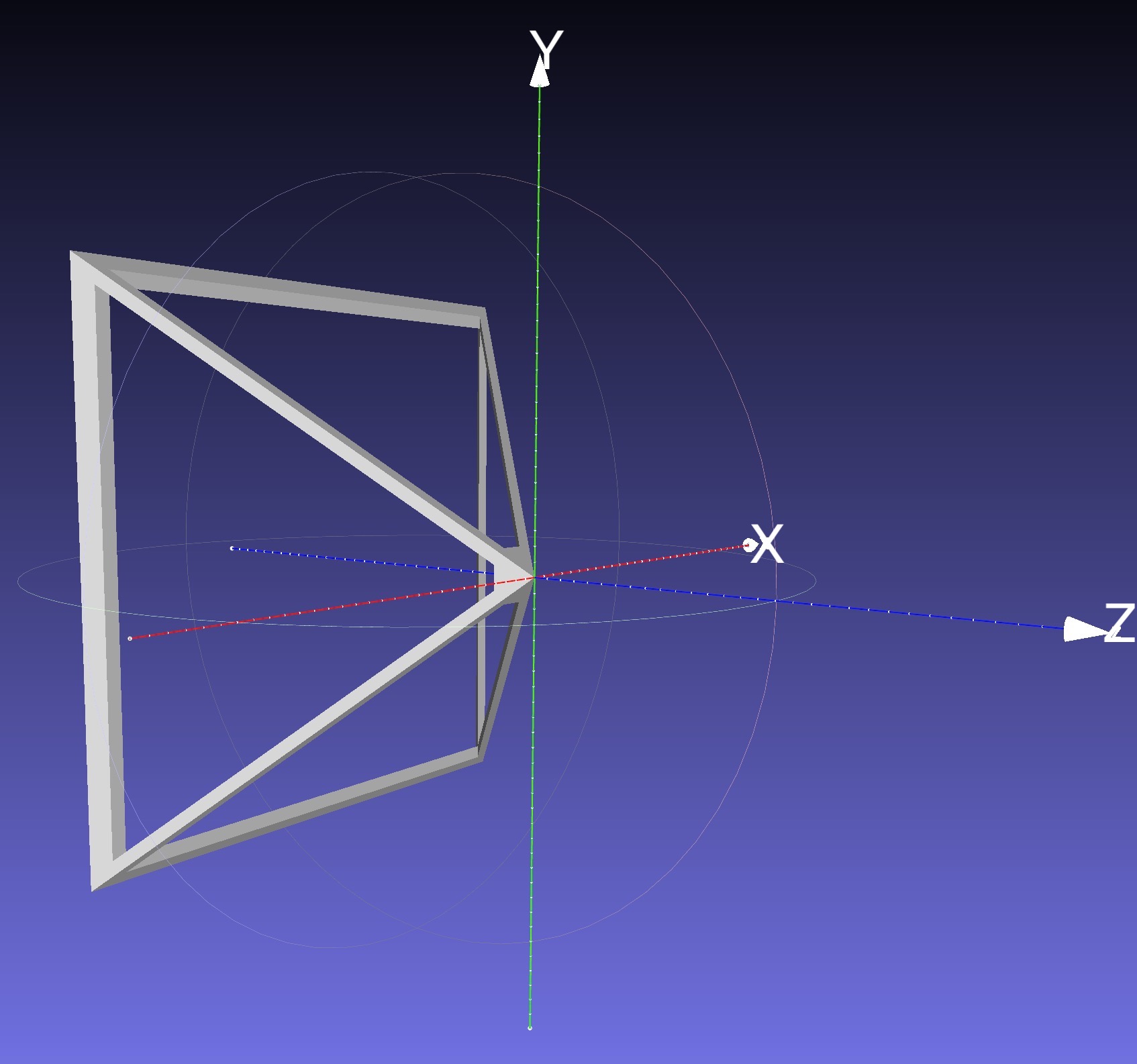
First, draw this mesh in the top-down viewport without applying any model transform to it. It should appear at the world origin, looking down the negative Z axis. Now, to account for the translation and the rotation of the camera, use the inverse of the view matrix (i.e., the camera matrix) as the model matrix when drawing the camera. This camera matrix should be multiplied onto the matrix stack before drawing the frustum. The following pseudocode should be added to the DRAW SCENE line of the top-down viewport portion of the first pseudocode of this task:
pushMatrix()
Camera matrix = inverse of the view matrix
multMatrix(Camera matrix)
Send the top matrix to the GPU
Draw the frustum
popMatrix()
The inverse of the view matrix can be obtained by inverting the output matrix of the glm::lookAt(...) function.
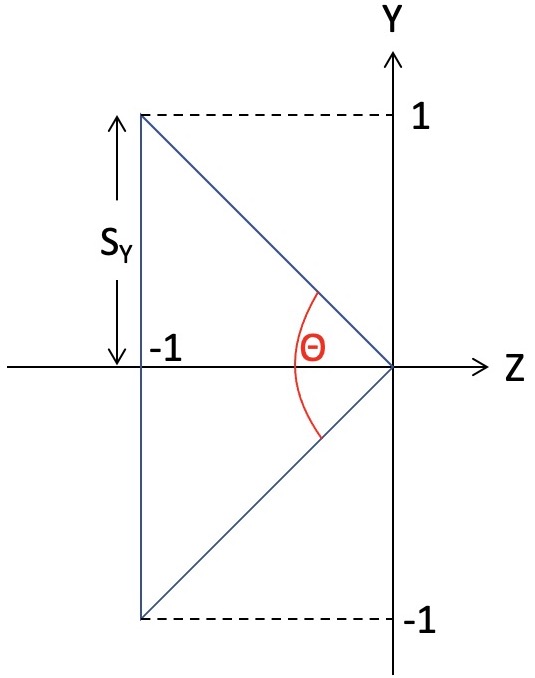
As shown in the right image above, the frustum’s extent is \(-1\) to \(+1\) in Y (as well as X) and \(0\) to \(-1\) in Z, which means that the shape of this frustum is correct only when the field of view is \(\theta=90\) degrees. To fix this, the following scales should be applied in X and Y:
\[ s_X = a \tan(\frac{\theta}{2}), \quad s_Y = \tan(\frac{\theta}{2}), \]
where \(a=\text{width}/\text{height}\) is the aspect ratio of the frame buffer. The angle, \(\theta\), is the field of view of the main camera, which depends on the current zoom level. The scale values \(s_X\) and \(s_Y\) should be applied to the modelview matrix stack before drawing the frustum.
Optionally, to make visible the parts of the frustum below the ground, disable the depth test while drawing the frustum:
glDisable(GL_DEPTH_TEST);
Transform and draw the frustum
glEnable(GL_DEPTH_TEST);Add a texture to the ground. You can use the vertex buffer approach from Lab 8 or use square.obj from Lab 9. You can also download a mesh (and add a citation in your readme), but note that some OBJ files may not come with normals or texture coordinates.
Total: 100 points
Failing to follow these points may decrease your “general execution” score. On Linux/Mac, make sure that your code compiles and runs by typing:
> mkdir build
> cd build
> cmake ..
> make
> ./A4 ../resources
If you’re on Windows, make sure that you can build your code using the same procedure as in Lab 0.
For this assignment, there should be only one argument. You can hard code all your input files (e.g., obj files) in the resources directory.
src/, resources/, CMakeLists.txt, and your readme file. The resources folder should contain the obj files and the glsl files.(*.~)(*.o)(.vs)(.git)UIN.zip (e.g., 12345678.zip).UIN/ (e.g. 12345678/).src/, CMakeLists.txt, etc..zip format (not .gz, .7z, .rar, etc.).