Due Tuesday 2/22 Wednesday 2/23 at 11:59 pm. You must work individually.
Learn and apply hierarchical 3D transformations using the matrix stack.
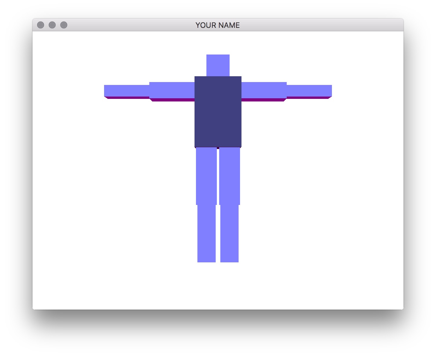
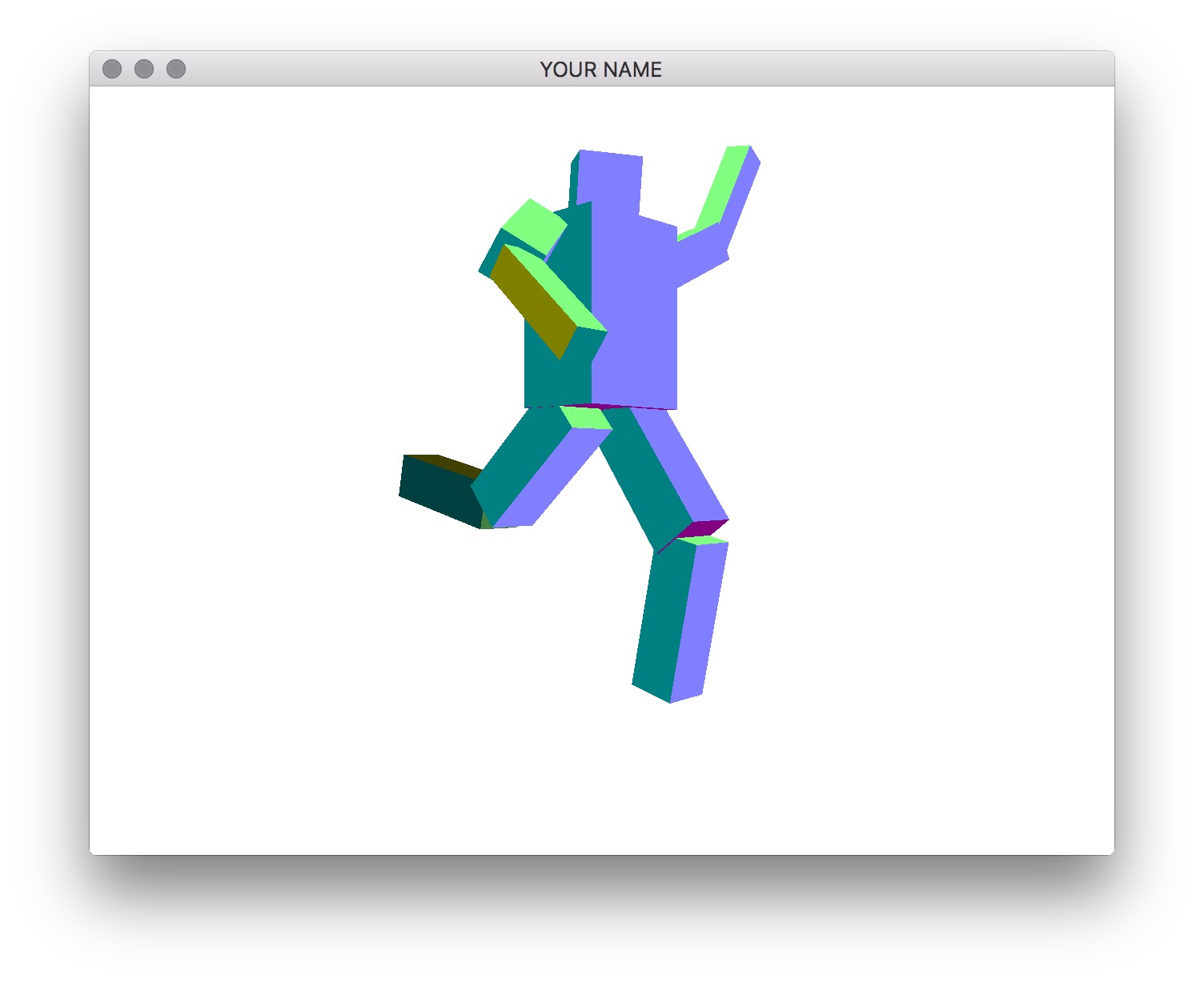
Write a program that allows you to create a robot that you can manipulate with the keyboard. You are free to create your own robotic character, but there should be at least 10 components in the robot, and the hierarchy should not be flat. For example, in the figures below, we have the following hierarchy:
The exact size, placement, and rotation of these components are up to you. These hard-coded values should be used in the init() function, not the render() function.
Start from your Lab 0 or Lab 4 code base.
A2 project folder and copy the the lab files and folders into it.CMakeLists.txt to change the project name (line 4).Shape, Program, etc.) to help you organize your code. You will be required to do this for later assignments.glfwSetCharCallback() function.You may skip ahead to Step 3 if you understand how to draw the components recursively. In this step, we are going to draw just the torso and the head without recursion so that you first understand how the transforms chain together.
In your render() function, first draw the torso and the head without any hierarchy:
prog->bind();
glUniformMatrix4fv(prog->getUniform("P"), 1, GL_FALSE, value_ptr(P));
// Draw the torso
MV->pushMatrix();
    MV->translate(...); // Where is the torso with respect to the world?
    MV->rotate(...); // This rotation applies only to the torso
    MV->scale(...); // This scale applies only to the torso
    glUniformMatrix4fv(prog->getUniform("MV"), 1, GL_FALSE, value_ptr(MV));
    shape->draw(prog);
MV->popMatrix();
// Draw the head
MV->pushMatrix();
    MV->translate(...); // Where is the head with respect to the world?
    MV->rotate(...); // This rotation applies only to the head
    MV->scale(...); // This scale applies only to the head
    glUniformMatrix4fv(prog->getUniform("MV"), 1, GL_FALSE, value_ptr(MV));
    shape->draw(prog);
MV->popMatrix();
prog->unbind();
Note: In this pseudocode, I’m assuming that P and MV are matrices. In your code, these may instead be pointers to MatrixStack, in which case you need to call glm::value_ptr(P->topMatrix()). (Don’t forget #include <glm/gtc/type_ptr.hpp>.) Alternatively, you can write &P->topMatrix()[0][0].
The indentation between push and pop helps with clarity but is not necessary. The first call to glUniformMatrix4fv() sends the projection matrix to the GPU. Then, we modify the modelview matrix, send it to the GPU, and then draw the shape. With this naive version, changing the position or the rotation of the torso does not modify the head.
To fix this, we now add some pushes and pops. Note that when we rotate the torso, we want the head to also rotate, but when we change the scale of the torso, we do not want to change the scale of the head. Therefore, we use an extra push/pop around the torso scale:
...
// Draw torso
MV->pushMatrix();
    MV->translate(...); // Where is the torso's joint with respect to the world?
    MV->rotate(...); // This rotation applies to torso and its children
    MV->pushMatrix();
        MV->translate(0, 0, 0) // Where is the torso's mesh with respect to the torso's joint?
        MV->scale(...);
        glUniformMatrix4fv(prog->getUniform("MV"), 1, GL_FALSE, value_ptr(MV));
        shape->draw(prog);
    MV->popMatrix();
    // Draw head
    MV->pushMatrix();
        MV->translate(...); // Where is the head's joint with respect to the torso's joint?
        MV->rotate(...); // This rotation applies to head and its children
        MV->pushMatrix();
            MV->translate(...) // Where is the head's mesh with respect to the head's joint?
            MV->scale(...);
            glUniformMatrix4fv(prog->getUniform("MV"), 1, GL_FALSE, value_ptr(MV));
            shape->draw(prog);
        MV->popMatrix();
    MV->popMatrix();
MV->popMatrix();
...
With the code above, translating and rotating the torso should also translate and rotate the head. Note that with this hierarchical version, the numbers used for translation/rotation/scale of the head may be different than with the previous non-hierarchical version, since now we are defining the head with respect to the torso.
Now we are going to create a general, hierarchical structure for drawing a robot with multiple limbs.
Create a class that represents a component. This class should contain the necessary member variables so that you can make a tree data structure out of these components. The root of the tree should represent the torso, which means that transforming the torso transforms everything else.
In addition to the member variables required for the tree hierarchy, the class should also have the following:
glm::vec3 representing the translation of the component’s joint with respect to the parent component’s joint.glm::vec3 representing the current joint angles about the X, Y, and Z axes of the component’s joint. (You may want to start with Z-rotations only.)glm::vec3 representing the translation of the component’s mesh with respect to its joint.glm::vec3 representing the X, Y, and Z scaling factors for the mesh.The drawing code should be recursive – in other words, in the render() function in main.cpp, there should be a single draw call on the root component, and all the other components should be drawn recursively from the root. In the main render() function, you should create an instance of the matrix stack class and pass it to the root component’s drawing function. Make sure to pass the matrix stack by reference or as a (smart) pointer.
The component’s rendering method should simply take the current state of the component and draw it. You should not create the robot hierarchy in this method. In other words, the scene setup must be done in main’s init() rather than in main’s render(). In your README, state where in your init() function (which line) should be modified to change the joint angles.
For this assignment, the 3D rotation of the joint should be represented simply as a concatenation of three separate rotation matrices about the x-, y-, and z-axes: Rx * Ry * Rz. The position of the joint should not be at the center of the box. For example, the elbow joint should be positioned between the upper and lower arms.
Add the functionality to select components and rotate the joints with the keyboard. When the appropriate key is pressed, the currently selected component, along with all of its descendants, should be rotated about the joint. For example, if the upper right arm is rotated, the lower right arm should rotate with it. The keyboard control should be as follows:
. (period): traverse the hierarchy forward, (comma): traverse the hierarchy backwardx/X: increment/decrement x angley/Y: increment/decrement y anglez/Z: increment/decrement z angleBy pressing the period and comma keys, you should be able to select different components in the hierarchy. You must draw the selected component so that it is distinguishable from unselected components. The x/X, y/Y, and z/Z keys should change the rotation angle of the selected component. In the left figure above, the torso is the selected component, and in the right figure, one of the lower legs is the selected component.
The traversal of the tree with the period and comma keys should be in depth-first or breadth-first order. Do not hardcode this traversal order – your code should be set up so that it works with any tree.
When drawing the selected component, change its size using the time variable. In the render() function, use the following GLFW call:
double t = glfwGetTime();This t variable should then be used to change the scale as follows:
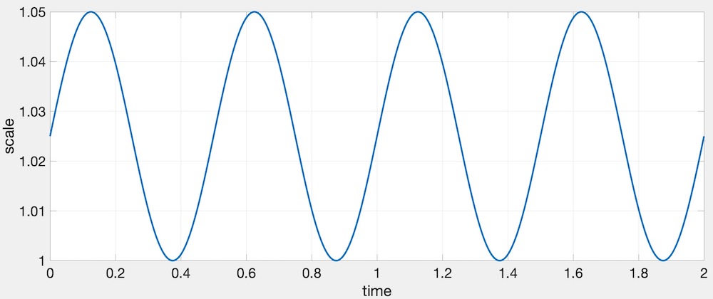
\[ s(t) = 1 + \frac{a}{2} + \frac{a}{2} \sin(2 \pi f t), \]
where \(a\) is the amplitude, \(f\) is the frequency, \(t\) is the time, and \(s\) is the resulting scale. The following values work well: \(a=0.05\), and \(f=2\). In other words, the scale increases by 5% twice a second. Here is a plot of this function.
Here is a working example:
Put a cube at each joint. The cube should be placed exactly where the joint is, so that when the joint is rotated, the cube does not translate. These cubes should not be in the hierarchy. Instead, they are simply extra things to be drawn while traversing the hierarchy.
For bonus, instead of drawing a cube, draw a sphere.
Rotate at least two components in place. This rotation should not be propagated to its children. At least one of the two should be a non-leaf component.
Set the Program class to be verbose by calling the setVerbose() function. If there is a GLSL compilation error, then you will see the error in the console. For example, if the varying variables of the vertex shader and the fragment shaders do not match up, it will tell you so. Make sure to set verbose to be false after debugging.
Use GLSL::checkError(GET_FILE_LINE); to find which OpenGL call caused an error. This function will assert if there were any OpenGL errors before getting to this line. You can use this to winnow down which OpenGL function is causing an error. For example, if you put this line at the top, the middle, and the bottom of your function, and if the assertion happens in the middle, you know that the error must be happening in the top half of your function. Once find exactly which OpenGL call is causing the error, you can Google the OpenGL function to figure out what caused the error. For example, maybe one of the arguments should not have been zero or null.
The GLSL compiler will silently optimize away any variables that are not used in the shader. If you try to access these variables at runtime, the program will crash, since these variables no longer exist in the shader. In this lab, when you move the computation of the normal to the GPU, the aNor variable no longer needs to be passed to the GPU, since it is computed in the shader. Therefore, you will have to comment out any reference to aNor from your C++ runtime code. Or, you can trick the GLSL compiler from optimizing away aNor by using it and disgarding it as follows:
  vec3 nor = aNor.xyz;
  nor.x = ...;
  nor.y = ...;
nor.z = ...;Task 2 is optional. If you have completed Task 3, you will get full points for Task 2.
init(), not render().Total: 100 + 5 points
Failing to follow these points may decrease your “general execution” score. On Linux/Mac, make sure that your code compiles and runs by typing:
> mkdir build
> cd build
> cmake ..
> make
> ./A2 ../resources
If you’re on Windows, make sure that you can build your code using the same procedure as in Lab 0.
src/, resources/, CMakeLists.txt, and your readme file. The resources folder should contain the obj files and the glsl files.(*.~)(*.o)(.vs)(.git)UIN.zip (e.g., 12345678.zip).UIN/ (e.g. 12345678/).src/, CMakeLists.txt, etc..zip format (not .gz, .7z, .rar, etc.).