

Due Tuesday 2/9 at 11:59 pm. You must work individually.
Create a program that reads in and renders a triangle mesh (of type .obj) to an image via software rasterization. You may use existing resources to load in the mesh and to write out an image. You must write your own rasterizer. In general the required steps for the program are:
Image class is used.Download the Assignment 1 base code, which has a mesh loader and an image writer. Compile and run the code by following the same set of commands as in Lab -1.
The mesh loader is an obj loader from http://github.com/syoyo/tinyobjloader, and the image writer is from http://github.com/nothings/stb.
When the mesh is loaded, the vertex positions are stored in the posBuf array as follows:
-----------------------------------------------------------------------------------------------
| x0 | y0 | z0 | x1 | y1 | z1 | x2 | y2 | z2 | x3 | y3 | z3 | x4 | y4 | z4 | x5 | y5 | z5 | ... <- posBuf array
-----------------------------------------------------------------------------------------------
| vertex 0 | vertex 1 | vertex 2 | vertex 3 | vertex 4 | vertex 5 |
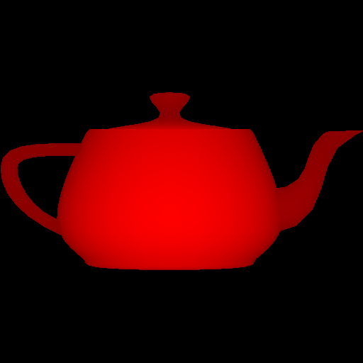
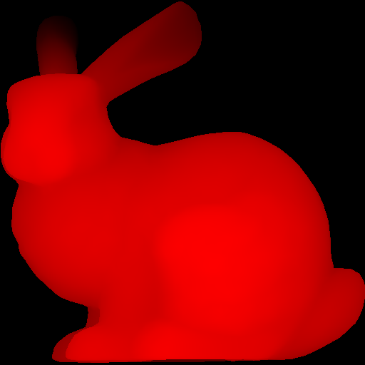
| triangle 1 | triangle 2 |Every three consecutive vertices in this array forms a triangle. In other words, every nine elements form the (x,y,z) coordinates of the three vertices of a triangle. (For now you can ignore the normal and the texture coords.) Example mesh files are included in the base code. In addition, there are numerous OBJ meshes on the web. For grading purposes, your program will be run using the provided Stanford Bunny and Utah Teapot.
Ultimately you will want each triangle to be represented in a C/C++ structure/class, with 3 vertices and a color per vertex. In addition, your triangle data should include a 2D bounding box, which will represent the triangle’s extents in image coordinates.
Add a command line argument to accept the following command line arguments.
For example, your program should be able to be run as follows:
> ./A1 ../resources/bunny.obj output.png 512 512 1(In Xcode, the 1st argument should be ../../resources/bunny.obj.) Add error checking to specify the required command line arguments if an incorrect number are given. Your program should not dump core if no input file is specified, or fail without an error message! Follow the golden rule; treat your user/grader/instructor the way you’d like to be treated as a user/grader/instructor.
Write code to convert each 3D coordinates into 2D image coordinates. Assume the camera is at the origin looking down the negative z axis. Make sure the object completely fills the image without any distortion. To do so, you need to compute the scale and translation factors as we discussed in class. Some tips for starting out:
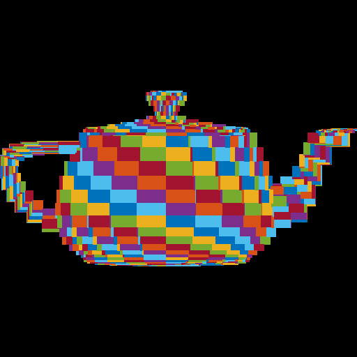
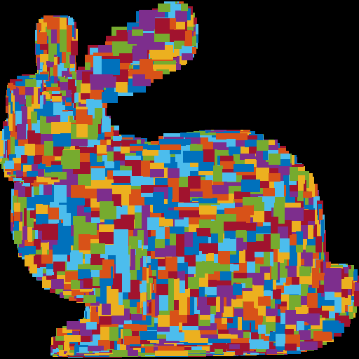
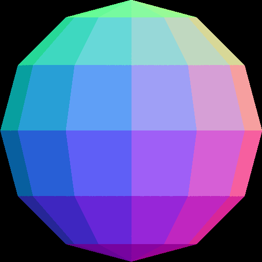
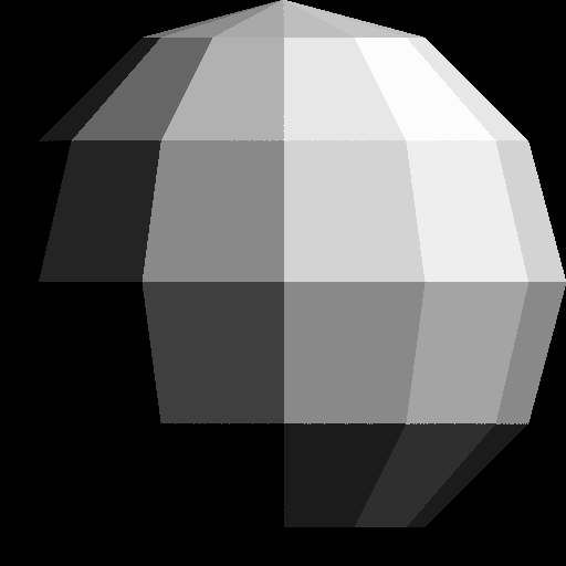
RANDOM_COLORS. For the ith triangle, the color should be RANDOM_COLORS[i%7].tri.obj, which contains a single triangle.First, write out the bounding box, rather than the triangles, to the image. If you do this with the provided tri.obj, sphere.obj, teapot.obj, and bunny.obj, you should see blocky images like below. Make sure the object takes up the whole image, is centered, and is undistorted (not stretched).
Make sure you test nonuniform window sizes. As shown below, the aspect ratio of the object should be preserved no matter what the image size is, and the object should fill out the image.


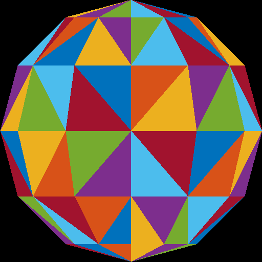
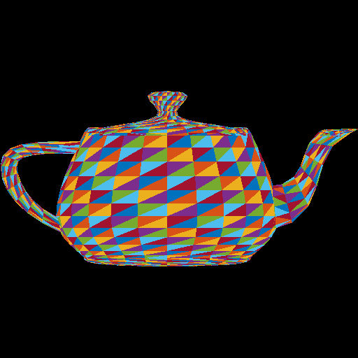
Once the bounding boxes are being displayed correctly, add the barycentric test to write out the triangles as in (optional) Lab 2. This should be the output when the “task” command line argument is set to 2. You should not see any gaps between the triangles.

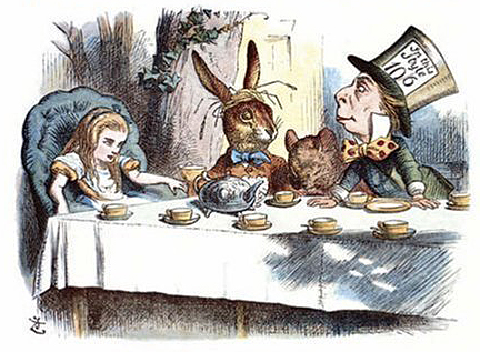
Here is another image of a bunny and a teapot, from Alice in Wonderland [Wikimedia].
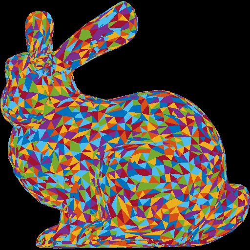
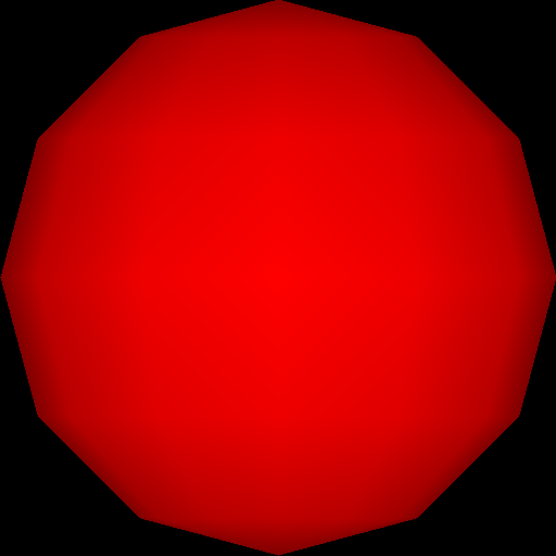
Instead of using random per-triangle colors, use random per-vertex colors. For each pixel inside each triangle, you need to interpolate the pixel’s color from the three vertices using the pixel’s barycentric coordinates.
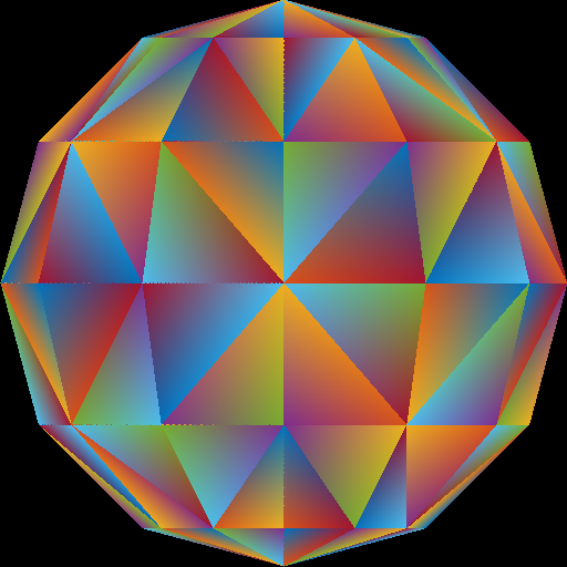
Optional information: Because of the way we are loading the mesh, the triangles do not share any vertices. For example, if we were to load a square consisting of four vertices and two triangles, we end up with six vertices – three for each of the triangles. In other words, we end up duplicating any shared vertices. Therefore, when we assign a color to each vertex, triangles having a vertex at a common position can have different colors assigned at this vertex position. For example, in the sphere image above, the center vertex is incident to eight triangles, and so it has been duplicated eight times, each time with a different random color. For further information check out indexed drawing.
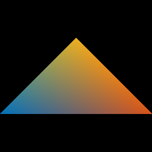
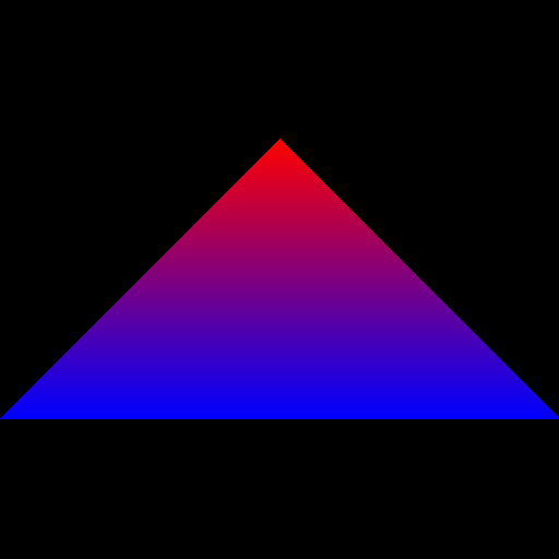
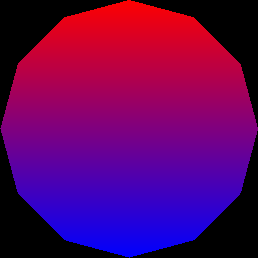
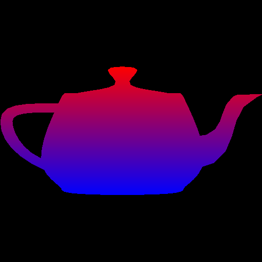
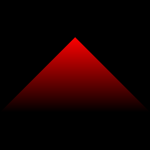
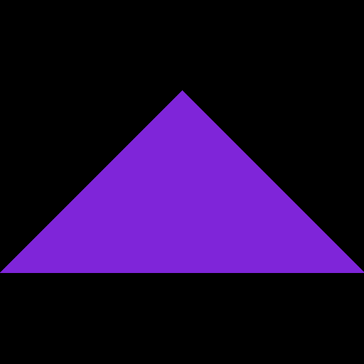
Next, use the y-value to linearly interpolate two colors: blue (0 0 255) and red (255 0 0). The color should vary smoothly from top of the object to the bottom of the object, rather than from the top of the whole image to the bottom of the whole image. In other words, the top tip of the triangle should be fully red.

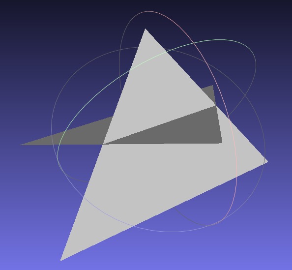
Now that you have interpolated colors, implement z-buffer tests. First, create a data structure to support z-buffer tests. Your z-buffer should be a separate buffer from your image pixel buffer, and it should be the same size as your pixel buffer. The z-buffer contains the z-coordinate of each pixel, which is interpolated from the z-coordinates of the three vertices using the pixel’s barycentric coordinates. Once you have z-buffer implemented, you should be able to render tri2.obj properly – the two triangles should be intersecting. In the right image below, the triangles are rendered with per-vertex colors.

Now, use the z value of the pixel as the red color (use 0 for both blue and green). To do this, you have to map the z-value to the range 0 to 255. If your z-buffer test is not working, you’ll see some strange results, since some pixels that are farther from the camera may be drawn on top of closer pixels.

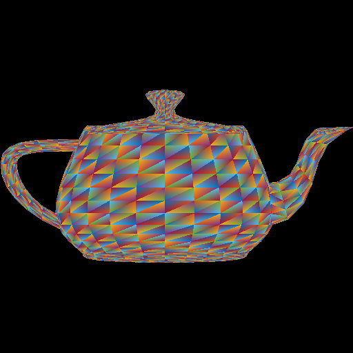
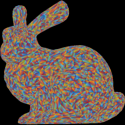
If your z-buffer is working, and if you’re interpolating the colors correctly, you should get the following results for the four obj files.
Make sure to pass your std::vector by reference rather than by value. (E.g., void foo(std::vector<float> &bar)) Otherwise, your program may become too slow. Since the Image class has an std::vector inside it, it should also be passed by reference.
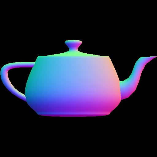
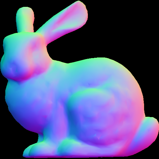
When we load the obj file, we are also loading the vertex “normals” of the mesh, in addition to the vertex positions. These are stored in the norBuf variable alongside the posBuf variable that are already being used. Store this “normal” information (a 3D vector) in each vertex. Then, when coloring the pixels, interpolate the normals of the three vertices of the triangle to compute the normal of the pixel.
A normal is a 3D direction, so its (x,y,z) values can be anything in the range \([-1, 1]\). To display the normal as a color, we need to map these values to the range \([0, 255]\). The expression for this mapping is 255 * (0.5 * x + 0.5); (repeat for y and z).
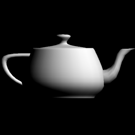
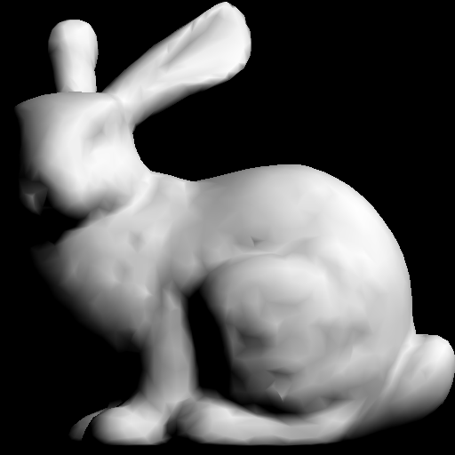
Finally, apply simple “lighting” calculation to compute the color of each pixel. After the normal \(\hat{n}\) has been computed at a pixel, compute the following:
\[ c = \text{max}(\hat{l} \cdot \hat{n}, 0), \quad \hat{l} = \frac{1}{\sqrt{3}}\begin{pmatrix}1\\1\\1\end{pmatrix}. \]
The “light” vector \(\hat{l}\) is the 3D direction of the light. Take the dot product between the normal and the light vector, and take the maximum of the result and zero. Without this zero, pixels that are facing away from the light will also be lit, which is not what we want. The resulting scalar, \(c\), should be applied to RGB equally:
\[ r = c, \quad g = c, \quad b = c. \]
Note that with the single triangle scene, we get an empty image because the triangle is facing away from the light.

main(), and remember to pass big data by reference.Total: 100 points
Failing to follow these points may decrease your “general execution” score.
On Linux/Mac, make sure that your code compiles and runs by typing:
> mkdir build
> cd build
> cmake ..
> make
> ./A1 <ARGUMENTS>
If you’re on Windows, make sure that you can build your code using the same procedure as in Lab -1.
src/, CMakeLists.txt, and your README file.(*.~), or object files (*.o).UIN.zip (e.g., 12345678.zip).UIN/ (e.g. 12345678/).src/, CMakeLists.txt, etc..zip format (not .gz, .7z, .rar, etc.).![[Wikimedia]](http://commons.wikimedia.org/wiki/File:John_Tenniel-_Alice%27s_mad_tea_party,_colour.jpg)