1. Overview
This project was inspired by a developer talk given by David Rosen from Wolfire Games at GDC 2014. The talk was titled "An Indie Approach to Procedural Animation" and emphasized using interoplation, physics, and IK to make up for little time and resources to make hand-crafted games. In particular, I wanted to try and implement the following from his talk:
- Procedurally animate climbing/grabbing with inverse kinematics
- Interpolation bone frames using cubic, bi-cubic and other schemes
- Skin and pose by own 3D model
Although I definitely couldn't get climbing to work as well as I wanted, I was able to get frame interpolation and Maya/C++ interaction working. The bulk of the time spent was creating a Maya ASCII file parser and then designing the IK system for climbing the "ladder". If I had more time, I would try to create a more constrained skeleton system with joints that only move at specific angles and axes.
2. Process
2.1 Working With Maya
I already had access to a fairly large code-base I developed (and borrowed) over the course of Intro to Graphics and the Animation class. This included code that helped me interact with OpenGL (nsgl), read in OBJ files (tiny_obj), perform complex linear algebra (Eigen), and draw a skinned model (from an earlier assignment). My first hurdle was creating my own 3D mesh that was rigged (skinning weights and a skeleton) and then use it in my project.
Since we used Maya for a single day in class, I figured I'd give it a shot as my means of creating my model. Creating the model was fairly simple, and with the help of some online guides I discovered skinning the mesh after rigging it was as simple as executing a single command. However, now I needed to take the mesh, rig, and skin weights and use them as part of my project.
2.1.1 Vertex Ordering
First off, Maya does not preserve vertex ordering when exporting the OBJ. So I needed to export my mesh, re-import it, and then re-rig it and add skinning weights again. Now the mesh has been "normalized" so-to-speak, and on the next export I could visually verify that each vertex did match up as expected.
2.1.2 Parsing Vertex Weights
I needed to read in the vertex weights and bones. Here, I made sure to save my Maya file in ASCII format (human-readable). This allowed me to peruse the save file and eventually determine how both the skin and bone structure was stored in maya. After writing a simple series of file parsers (and later a more comprehensive system), I was able to reconstruct both the bones of the skeleton and the weights per vertex.
The idea is to search for the "skinCluster" (the weight of each vertex and associated bone for each weight) by name (here it is called "Skin"). Here is an example of what a skinCluster looks like in a Maya file:
createNode skinCluster -name "Skin";
   setAttr -size 578 ".weightList";
   setAttr -size 4 ".weightList[0].weights";
   setAttr ".weightList[0].weights[0]" 0.4413976939404502;
   setAttr ".weightList[0].weights[1]" 0.071369962381840193;
   setAttr ".weightList[0].weights[2]" 0.053775061290240934;
   setAttr ".weightList[0].weights[5]" 0.43345728238746867;
   setAttr -size 4 ".weightList[1].weights";
   ...
   setAttr -size 4 ".weightList[281].weights[0:3]"  0.45212502823863626
      0.013426650545438696 0.5308990853774499 0.0035492358384751816;
   ...
   setAttr -size 4 ".weightList[577].weights[12:15]"  0.064914906827006236
      0.01446226454503402 0.46174956886400037 0.45887325976395943;
   setAttr -size 16 ".bindPreMatrix";
   setAttr ".bindPreMatrix[0]" -type "matrix" 2.2204460492503121e-16
      -0 -0.99999999999999978 -0
   ...
Here, "weightList[i].weights[j] f" corresponds to the i-th vertex having a weight of f for bone j, where j is the unique id of that bone. Similarly, "weightList[i].weights[j:k] f1 f2 ..." corresponds to the i-th vertex having a weights of f1, f2, ... for bones j to k, where j through k are the unique id's that correspond to the range of bones j through k. Once we hit "bindPreMatrix" we can stop adding vertices (or we could keep track of how many vertices have been parsed).
2.1.3 Parsing the Mesh's Skeleton
The skeleton was a bit trickier since the information is a bit more spread out than with the skinCluster. First, I need a list of all of the bones by name and their associated integer id. Then I need to attain the definition of each bone, its parent (if any) and the bind pose matrix. Each skeleton has a unique name (here I call it "BindPose") and each bone is "connected" to that skeleton.
Near the bottom of the Maya file was a list of connections for the skeleton system:
...
connectAttr "TorsoBase.message" "BindPose.members[0]";
connectAttr "Neck.message" "BindPose.members[1]";
connectAttr "RArmBase.message" "BindPose.members[2]";
connectAttr "RArmElbow.message" "BindPose.members[3]";
...
connectAttr "RLegAnkle.message" "BindPose.members[15]";
...
I was able to verify that "BoneName.message BindPose.members[i]" hints to the reader that the bone called BoneName is the i-th bone of BindPose (this corresponds exactly to the indices given by the skinCluster weightList). Somewhere else in the file are definitions for each bone asociated with the skeleton:
createNode joint -name "Neck" -parent "TorsoBase";
   ...
   setAttr ".bindPose" -type "matrix" 2.2204460492503131e-16
      0 1.0000000000000002 0 0 1 0 0 -1.0000000000000002 0
      2.2204460492503131e-16 0 0.0032850998072331316
      0.12060632373051638 8.0278402758056622 1;
   setAttr ".radius" 0.5;
   ...
Each bone has a name, possibly a parent, and then a "bindPose". Matrices in this ASCII format are specified column-first (discovered by trial and error), so reading them into an eigen matrix is pretty easy to do.
2.1.4 tiny_obj_loader Vertex Expansion
tiny_obj_loader may add extra vertices when loading an OBJ file. So I added some extra structure to the loader so that I would keep track of how the added vertices mapped to the original set of vertices. With this map, I could reconstruct which vertices got which weights from each bone.
2.1.5 Parser in Action
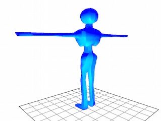
Finally, I had a system for parsing a Maya file for skinning weights and a skeleton and then got this working with an associated OBJ file. At this point, I can load and view my model, as shown in Figure 2.1.A.
2.2 Building a Skeleton System
My next task was to borrow from past labs and lecture material to create a working skeletal system that I could move and tweak and ultimately use for solving IK problems and animate movement. Since I alread have my skeleton built from parsing the Maya file, all I needed to do was make sure the bones actually effected movement in the correct way.
2.2.1 Bone Hierarchies
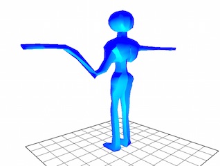
At this point my skeleton system is rudimentary at best. If I try to modify the left arm's rotation, then bones down the hierachy are not appropriately effected, as shown in Figure 2.2.A.
Each bone has a bind matrix that takes a point in the bone's current coordinate spaces and moves it to the world coordinate space. So for each bone I then needed to extract the position of each bone relative to its parent (the origin in the case of the root bone) and the rotation of the bone with respect to each bone's parent. To do this, I though about it mathematically:
Let P be the vector that points to the parent's origin wrt the current bone, and let R be the rotation of bone wrt its own coordinate space. Every 'E' is a coordinate transformation. Ei is the i-th bone in the hierarchy below the root (E1) on its way to the current bone (Ek).

P = (vector that points to parent's origin wrt child)
P = -(vector that points to child's origin wrt parent)
P = -E(child to parent) * (child's origin)
P = -E(parent to world)-1 * E(child to world) * (child's origin)

R = R
R = I * R
R = (E1 * ... * Ek-1 * P)-1 * (E1 * ... * Ek-1 * P) * R
R = (E1 * ... * Ek-1 * P * I)-1 * (E1 * ... * Ek-1 * P * R)
R = (pose with no rotation)-1 * (bindPose matrix)
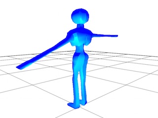
With the above math and a way to calculate the current pose matrix of each bone, the skeleton can now bend as expected as shown in Figure 2.2.B.
2.2.2 Posing the Model in Maya
The next step was being able to create poses in Maya and then loading them in my program. However, this can't be done easily through the animation tools in Maya. For animation, poses are setup as a series of interpolated curves from the original bind pose. To remedy this, one needs to select the bone hierarchy after posing it and run the following command:
dagPose -bp -save
Now a new bind pose is created for the skin in addition to any that have already been created. What is nice is that Maya will actually save the bind matrices w.r.t. to world coordinates which can be easily parsed for the ASCII maya save file.
2.2.3 Interpolating Poses
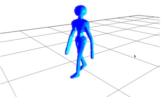
During this time I made a few adjustments to the character model, changed some skinning weights, and created a standing pose and two walking poses. From here I merely interpolated bone rotations between world frames to arrive at a simple walking animation as shown in Figure 2.2.C.
2.3 Ceres Solver and Realtime IK
Here I will discuss how I used Google's Ceres Solver to make my model "climb" up a ladder.
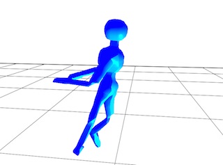
2.3.1 Basic Constraints on Movement
To provide some basic constraints to my movement, I hinted to Ceres to try and keep rotations relatively unchanged (stiffness) and made four joints stay in four designated locations. This, in conjunction will allowing Ceres to change the position of the model leads to the model "climbing" up the ladder with nothing extra added. However, this lead to some funny results with legs breaking backwards and weird twisting at joints as shown in Figure 2.3.A.
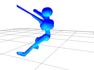
2.3.2 Additional Constraints with Maya
Maya allows us to specify more data ("Attributes") on data objects. So for each joint, I added parameters that detailed the "stiffness" of a joint (how much it was willing to rotate out of place) and a preferred rotational axis. Additionally, the torso is set to be a certain distance away from the "wall" and the spine wants to be "straight" up and down. With these changes implemented, we arrive at a fairly decent solution to climbing as shown in Figure 2.3.B.
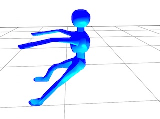
2.3.3 Realtime IK Solutions
Each joint movement would normally take about 1-2 seconds of computation time by the Ceres Solver to get an optimal orientation. However, it would be best if solutions could be determined in about a few draw frames (20-200ms). First I rebuilt Ceres so it could use multi-threaded solving. Then I reduced a bunch of thresholds on solution specificity by several orders of magnitude and the number of times it could try solving the problem by about half. With all of this included the solver seems to work without any hesitation at finding reasonable solutions within a few draw frames. However, the solution arrive at is not always optimal as shown in Figure 2.3.C.
2.3.4 Joint Springs
We can help Ceres Solver arrive at more optimal solutions by specifying joint springs. However, at this point I ran out of time and could not fully implement joint springs into the solver.
3. Final Result
3.1 Broken Bones
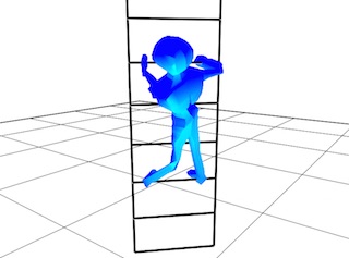
The skeleton system I had put in place was just not constrained enough. Because I used quaternions exclusively, I wasn't getting very good solutions and I had a hard time analyzing things like twist and axis rotation deviation in the solver. I had begun work on a more constrained skeleton built just for the solver, but I ran out of time and couldn't fully implement it into the system.
Without having a more constrained skeleton (and poor management of source code changes) we arrive at the bone-breaking climber as shown in Figure 3.1.1.
3.2 Maya Interaction and Interpolation
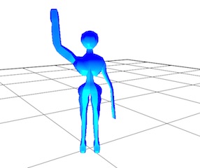
The upside to this project is that I learned a lot more about how Maya works and how to use it more effectively with my projects. I build a Maya file parser to read in my mesh's various attributes and used it to create simple animations. Here's Henry waving goodbye (Figure 3.2.1).
3.3 Project In Action
The project has a few controls:
Keyboard Controls:

 Camera:
   WASD  - move character around
   Shift + Drag Mouse Y axis
         - zoom camera in an out

 Climbing:
   C     - toggles whether Henry is Climbing.
   IOKL  - performs IK on Henry's various limbs to climb the ladder
   T     - have Ceres try to find a more optimal solution

 Misc:
   /     - toggles debug mode
   1     - toggles whether Henry is waving at you
4. Resources and References
Primary Sources:
- This project made extensive use of Eigen, a C++ Math library
- I used Google's Ceres Solver for skeleton positioning.
- Shinjiro Sueda for lots of sample code and advice.
- I used tinyobjloader for testing and building shapes on-the-fly.
- This application is built on OpenGL and GLUT
- I used Maya 2015 as my model editor and rigger.