CS 3843 Spring 2011
Computer Organization
Lecture 3
Digital Logic Design II
Topics for today:
- Examples of building combinational circuits.
- Memories.
- Java program for doing ripple-carry addition
Examples of Building Circuits
Let's look at some of the logical and arithmetic operations a computer
does, and see how they might be implemented as combinational circuits.
- Bit equality. How do we test whether two bits a and b
are equal?
The truth table looks like this:
a  b  a==b
0  0   1
0  1   0
1  0   0
1  1   1
What does the Karnaugh
map for this function look like?
What is a minimal sum-of-products (SOP) for this function?
What would a combinational circuit for this function look like?
- Integer equality (word equality). For an n-bit
integer, there are 2n inputs: n-bit
integers a and b represented by bits
a0...an-1 and
b0...bn-1. The output
is 1 if a==b, 0 otherwise. How would we construct such
a circuit? For instance, if n=2, then the truth table looks
like this:
a1 a0 b1 b0  a==b
0  0  0  0    1
0  0  0  1    0
0  0  1  0    0
0  0  1  1    0
0  1  0  0    0
0  1  0  1    1
0  1  1  0    0
0  1  1  1    0
1  0  0  0    0
1  0  0  1    0
1  0  1  0    1
1  0  1  1    0
1  1  0  0    0
1  1  0  1    0
1  1  1  0    0
1  1  1  1    1
How might this function be useful in a computer? It can be used to
implement the == operator in Java.
What does the Karnaugh map for this function look like?
What is a minimal SOP for this function?
One way to implement this function is to build a circuit based on the
minimal SOP. But what if n=3? Then there are 6 variables.
The K-map would have 64 0s and 1s. If n=4, then there are eight
variables. The K-map would have 256 0s and 1s. On modern machines,
this circuit would have to work for n=32. That would yield a
K-map with 18,446,744,073,709,551,616 0s and 1s, and keeping track of the
adjacencies would be difficult on two-dimensional paper.
Another way to implement this function is to link together many 1-bit
equality circuits. How would you do that?
- Bit multiplexor (MUX). A multiplexor is a device for choosing one of
two inputs based on a third control input. So there are three
inputs: a, b, and s, and one output which is
a, if s==1, or b, if s==0.
The truth
table looks like this:
s  a  b  MUX(a,b,s)
0  0  0      0
0  0  1	     1
0  1  0      0
0  1  1      1
1  0  0      0
1  0  1      0
1  1  0      1
1  1  1      1
How might this function be useful in a computer? Think of it as a
logic-level version of the if/else statement. It
basically says if (s) output = a; else output = b;
- Word-level multiplexor.
This function is a multi-output version of the bit multiplexor, using
a control input to pass either an n-bit word a or
an n-bit word b. There are 2n inputs:
n-bit words a and b represented by
bits a0...an-1
and b0...bn-1.
The outputs c0...cn-1
are the corresponding bits of a if s==1, or b
if s==0.
For n=2, the truth table looks like this:
s  a1 a0 b1 b0  c0  c1
0  0  0  0  0   0  0
0  0  0  0  1   0  1
0  0  0  1  0   1  0
0  0  0  1  1   1  1
0  0  1  0  0   0  0
0  0  1  0  1   0  1
0  0  1  1  0   1  0
0  0  1  1  1   1  1
0  1  0  0  0   0  0
0  1  0  0  1   0  1
0  1  0  1  0   1  0
0  1  0  1  1   1  1
0  1  1  0  0   0  0
0  1  1  0  1   0  1
0  1  1  1  0   1  0
0  1  1  1  1   1  1
1  0  0  0  0   0  0
1  0  0  0  1   0  0
1  0  0  1  0   0  0
1  0  0  1  1   0  0
1  0  1  0  0   0  1
1  0  1  0  1   0  1
1  0  1  1  0   0  1
1  0  1  1  1   0  1
1  1  0  0  0   1  0
1  1  0  0  1   1  0
1  1  0  1  0   1  0
1  1  0  1  1   1  0
1  1  1  0  0   1  1
1  1  1  0  1   1  1
1  1  1  1  0   1  1
1  1  1  1  1   1  1
The general n-bit multiplexor function would be used in a computer
for multiplexing words (e.g. integers) rather than just bits.
Since this function has multiple outputs, we don't know yet how to make
a K-map for it. One way would be to draw two 5-variable K-maps, with
the first representing c0 and the second representing
c1. This drawing would have 64 0s and 1s.
An easier way to make a circuit out of this mess would be to combine
two 1-bit multiplexors.
- 4-input multiplexor. A 4-input multiplexor chooses from one of four
inputs based on two control inputs. The control inputs can be thought of
as a 2-bit number, from 0 through 3, that chooses one of the four inputs.
So there are six inputs: i0, i1, i2, i3, s0, and s1. The truth table looks
like this:
s0 s1 i0 i1 i2 i3  output |    s0 s1 i0 i1 i2 i3  output
0  0  0  0  0  0     0    |    1  0  0  0  0  0     0
0  0  0  0  0  1     0    |    1  0  0  0  0  1     0
0  0  0  0  1  0     0    |    1  0  0  0  1  0     1
0  0  0  0  1  1     0    |    1  0  0  0  1  1     1
0  0  0  1  0  0     0    |    1  0  0  1  0  0     0
0  0  0  1  0  1     0    |    1  0  0  1  0  1     0
0  0  0  1  1  0     0    |    1  0  0  1  1  0     1
0  0  0  1  1  1     0    |    1  0  0  1  1  1     1
0  0  1  0  0  0     1    |    1  0  1  0  0  0     0
0  0  1  0  0  1     1    |    1  0  1  0  0  1     0
0  0  1  0  1  0     1    |    1  0  1  0  1  0     1
0  0  1  0  1  1     1    |    1  0  1  0  1  1     1
0  0  1  1  0  0     1    |    1  0  1  1  0  0     0
0  0  1  1  0  1     1    |    1  0  1  1  0  1     0
0  0  1  1  1  0     1    |    1  0  1  1  1  0     1
0  0  1  1  1  1     1    |    1  0  1  1  1  1     1
0  1  0  0  0  0     0    |    1  1  0  0  0  0     0
0  1  0  0  0  1     0    |    1  1  0  0  0  1     1
0  1  0  0  1  0     0    |    1  1  0  0  1  0     0
0  1  0  0  1  1     0    |    1  1  0  0  1  1     1
0  1  0  1  0  0     1    |    1  1  0  1  0  0     0
0  1  0  1  0  1     1    |    1  1  0  1  0  1     1
0  1  0  1  1  0     1    |    1  1  0  1  1  0     0
0  1  0  1  1  1     1    |    1  1  0  1  1  1     1
0  1  1  0  0  0     0    |    1  1  1  0  0  0     0
0  1  1  0  0  1     0    |    1  1  1  0  0  1     1
0  1  1  0  1  0     0    |    1  1  1  0  1  0     0
0  1  1  0  1  1     0    |    1  1  1  0  1  1     1
0  1  1  1  0  0     1    |    1  1  1  1  0  0     0
0  1  1  1  0  1     1    |    1  1  1  1  0  1     1
0  1  1  1  1  0     1    |    1  1  1  1  1  0     0
0  1  1  1  1  1     1    |    1  1  1  1  1  1     1
That is truly a horrible truth table, but sometimes we have to solve
truth tables like that, so let's see what a 6-variable K-map would look
like:
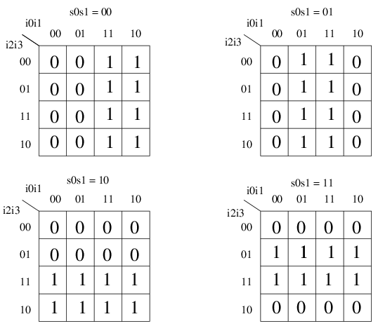
Hey, that's not so bad when you look at it as a K-map.
Why would you want such a circuit? This is the basis of how array indexing
is implemented in a high-level programming language like Java. You provide
a k-bit array index and get one of 2k items
from memory. Something has to do that conversion from the index to the
location of the items, and in a computer that something is a multiplexor.
- Full adder. We did this one last time, but let's see it again.
How would we do this using NANDs instead of ANDs, ORs, and NOTs?
Memories
So far, we have seen only combinational circuits, where the inputs completely
determined the outputs. There's no notion of memory, i.e., state. What if
we wanted to design a circuit such that the output is a stored bit, rather
than some function of the inputs? That can't be done with combinational,
i.e. acyclic, circuits, but it can be done if we allow circuits to have
cycles.
R-S Latch
The follow circuit is called an R-S latch:
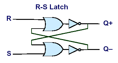
When both R and S are set to 1, the output of the circuit is a single
stored bit that can be thought of as constantly looping through the
circuit.
To store a one, we bring R down to 0.
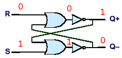
To store a zero, we keep R at 1 and bring S down to 0.
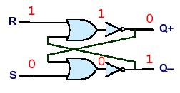
We can build arrays of latches to hold words (e.g. integers). An array of
latches is called a register. Special registers in the CPU are
made visible to the architecture, i.e., machine language instructions can
access special CPU registers.
6T SRAM Cell
Note that an R-S latch consumes 8 transistors, 4 for each NAND gate.
This is fine for registers, but for large memories we might want a smaller
circuit. Think of a large memory as a 2-dimensional array of single-bit
memory cells. It's 2-dimensional because chips are 2-dimensional.
Using multiplexors, we translate a memory address into one of many possible
columns and one of many possible rows. The bit corresponding to the
given column and row can be picked out and read or modified.
A 6-transistor SRAM cell looks like this:
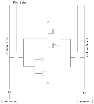
The two inverters (i.e., the four middle transistors) provide storage for
a single bit. Think of the bit as continously going around and around
the two inverters in a counter-clockwise manner. The bit is the output
of the top inverter, and the complement of the bit is the output of the
bottom inverter as well as the input to the top inverter. The following
occurs when we want to read the bit stored in this SRAM cell:
- There are two column select lines. Each one is
precharged to 1 by the column selector logic. (All other column
select lines in the memory array would be reset to 0.)
- The row select line for this cell is set to 1 by the row decoder logic.
(All other row select lines would also be reset to 0.)
- At this point, the current from the row select line flows to two NMOS
transistors which begin to allow the bit and its inverse to flow out of the
SRAM cell to the column select lines. One of the column select lines is
slowly pulled to 0. The process is slow because the tiny SRAM transistors
have to drive the substantial column select lines that have been precharged
to 1. An analog device called a senseamp at the bottom of the
column select lines quickly detects any difference in current and decides
that the bit is a 0 if the left column select line is going to 0, or a 1
if the right column select line is going to 0.
The following occurs if we want to write a bit x to the SRAM
cell:
- The row select line is set to 1, allowing current to flow between
the column select lines and the inverters.
- The left column select line is driven to x and the right
line is driven to the complement of x. The beefier drivers
are stronger than the inverters, so the value currently going around the
inverters is replaced with the new value.
Java program for doing ripple-carry addition
This Java program does ripple-carry addition, as well as subtraction,
on 32-bit integers.
import java.lang.*;
import java.io.*;
import java.net.*;

public class add {

public static void main (String args[]) {
	int a = 1234;
	int b = 5678;
	int c;
	boolean A[] = new boolean[32];
	boolean B[] = new boolean[32];
	boolean C[] = new boolean[33];

	int2bin (a, A, 32);
	int2bin (b, B, 32);
	ripple_carry_add (A, B, C, 32);
	c = bin2int (C, 33);
	System.out.println (c);

	subtract (A, B, C, 32);
	c = bin2int (C, 33);
	System.out.println (c);
}

// convert integer x to n-bit Boolean array v

static void int2bin (int x, boolean v[], int n) {
	for (int i=0; i<n; i++) {
		v[i] = (x & 1) == 1;
		x /= 2;
	}
}

// convert n-bit Boolean array v to integer and return it

static int bin2int (boolean v[], int n) {
	int x = 0;
	for (int i=n-1; i>=0; i--) {
		x *= 2;
		if (v[i]) x++;
	}
	return x;
}

// do a ripple-carry add on n-bit Boolean arrays A and B, storing the result
// in n+1-bit Boolean array C

static void ripple_carry_add (boolean A[], boolean B[], boolean C[], int n) {
	boolean carry;

	// no carry in; 2-bit parity is XOR

	C[0] = A[0] ^ B[0];

	// two-bit carry is AND

	carry = A[0] && B[0];

	// add corresponding bits of the array, along
	// with the carry generated initially or from previous
	// iterations of the loop

	for (int i=1; i<n; i++) {
		C[i] = parity (A[i], B[i], carry);
		carry = majority (A[i], B[i], carry);
	}

	// n'th bit is the carry out of the loop

	C[n] = carry;
}

// return the parity of x, y, and z

static boolean parity (boolean x, boolean y, boolean z) {
	return x ^ y ^ z;
}

// return the majority of x, y, and z

static boolean majority (boolean x, boolean y, boolean z) {
	return (x && y) || (x && z) || (y && z);
}

// subtract n-bit Boolean array B from A, placing result in n+1-bit array C
// i.e. C = A - B

static void subtract (boolean A[], boolean B[], boolean C[], int n) {
	boolean complementB[] = new boolean[n];
	boolean negativeB[] = new boolean[n+1];
	boolean one[] = new boolean[n];
	int i;

	// we'll subtract B from A by adding -B to A
	// first we have to find -B, which is the bitwise complement
	// of B plus 1

	// find the logical complement of B

	for (i=0; i<n; i++) complementB[i] = ! B[i];

	// make a 1

	one[0] = true;
	for (i=1; i<n; i++) one[i] = false;

	// find the negation of B

	ripple_carry_add (complementB, one, negativeB, n);

	// find A + (- B)

	ripple_carry_add (A, negativeB, C, n);
}
};


